Electro-Hydraulic Basics: Automating Processes with Counter (3 of 3)
1. Introduction
This is the last part of the automating processes sub series for electro-hydraulic circuit. In the previous blog, we discuss a circuit that automates a process within a specific cycle repetition. We based our circuit from the problem or scenario. The problem is describe as
Metal components are to be cleaned in an acid bath. These components are placed in a basket which is hung from a hook on a double-acting cylinder. A single actuation of a pushbutton causes the basket to be continuously lowered into and pulled out of the acid bath. The sequence stops automatically after 10 cycles. Sensors S0 and S1 check the fully retracted and extended positions, respectively, of the cylinder.
We used a hydraulic double-acting cylinder to achieve the dipping of the metal component in an acid bath. The metal submerge to the acid bath by 10 cycles. The circuit and the simulation is presented with details in next sections.
2. Circuit and Simulation
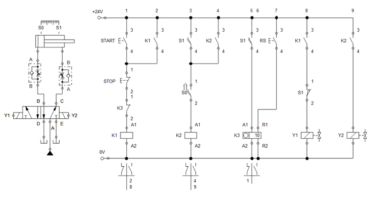
Figure 1: Electro-Hydraulic Circuit
Similar to the previous blog, A double solenoid 5/2 way directional control valve controls the movement of the cylinder. We limit the speed of the double-acting cylinder using a one-way flow control valve. For the electrical controller, we used a pair of push button, relay and solenoid. Also, a relay counter is used to limit the number of repetition of the dipping process. In the ladder 1 and 2, we connect the start button and relay contact K1 in parallel so that when start button is pressed, contact K1 sustain activation. The combination is then series with the stop button, contact K3 and relay K1. Both stop button and contact K3 can deactivate the process. Relay K1 is linked to the the activation of solenoid Y1. Solenoid Y1 extends the cylinder. In ladder 3 and 4, we set when will the cylinder retract to initial position. The combination of sensor S1 and S0 activates relay K2. Contact K2 is in parallel with S1 so that relay K2 sustains activation. Contact K2 is connected to solenoid Y2. Solenoid Y2 commands the cylinder to retract.
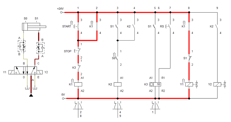
Figure 2: Start button is pressed.
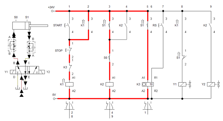
Figure 3: Cylinder is fully extended
When the start button is activated, electricity energized the relay K1 that enables K1 contact to close. Solenoid Y1 is energized after relay contact K1 closes. Solenoid Y1 open port B of the 5/2 way directional control valve. This is shown in Figure 2 and 3. Once cylinder reached full extended length, Relay K2 and counter K3 is activated simultaneously. Relay K2 enables Y2 to close port B and open port C of the 5/2 way directional control valve.
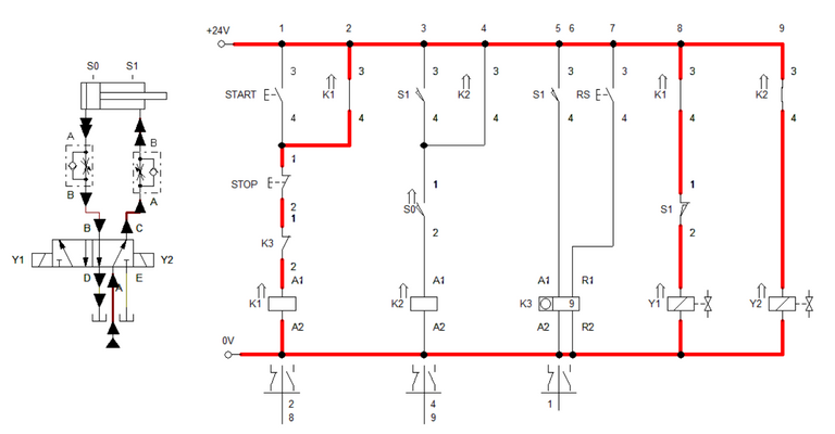
Figure 4: Cylinder returns to initial position.
When solenoid Y2 is activated, the cylinder retracts to the initial position. At the same time, counter K3 is deactivated and set count is reduced by 1. As the cylinder reaches retracted position, it reextend hence relay K1 is still engaged. The process of extending and retracting continues until the relay counter stops activating. If we want to deactivate the process midway, we press the stop button. RS button is used to reset the relay counter. The Simulation is shown in Figure 5.
Figure 5: Simulation
3. Conclusion
In this blog, we created a basic automation circuit with counter, shown in Figure 1. With the use of counter, a process can repeat depending on the set counts in the counter. The counter stops the system once the set number of repetition is achieved. The important point to remember in automating with counter is to place the counter relay contacts at the exact place so that it stops and repeat the process.
4. References
[1] Hydraulic Basic Level. online access
[2] Hydraulic Advance Level. online access
[3] Electro-Hydraulic Basic Level. online access
[4] Electro-Hydraulic Advance Level. online access
(Note: All images and diagram in the text are drawn by the author (@juecoree) except those with separate citation.)
If your are interested in pneumatic and hydraulic series, you can read:
Pneumatic and Electro-pneumatic
1. Pneumatic Basics: Direct Control
2. Pneumatic Basics: Indirect Control
3. Pneumatic Basics: AND and OR Logic
4. Pneumatic Basics: Memory Circuit and Speed Control
5. Pneumatic Basics: Dependent control
6. Pneumatic Basics: Multiple Actuators
7. Electro-pneumatic Basic: AND and OR Logic
8. Electro-pneumatic Basics: Interlocking, Latching and XOR logic
9. Electro-pneumatic Basics: Distribution of Workpiece
10. Electro-pneumatic Basic: Ejecting a workpiece
11. Electro-pneumatic Basics: Basic Automation
12. Electro-pneumatic Basics: Automation with Counter
12. Electro-pneumatic Basics: Automating with Timer
13. Electro-pneumatic Basics: Cementing Press (Time Dependent Control)
14. Electro-pneumatic Basics: Embossing Device
15. Electro-pneumatic Basics: Bending Device
16. Electro-pneumatic Basics: Introduction to Logic Module
17. Electro-pneumatic Basics: Automating with Logic Controller
18. Electro-pneumatic Basics: Logic Controller for Multiple Actuators
19.Electro-pneumatic Basics: Time-dependent control with Logic Controller.
Hydraulics and Electro-Hydraulic
20. Hydraulic Basics: Direct Control
21. Hydraulic Basics: Indirect Control
22. Hydraulic Basics: Dual Pressure Value and the AND Logic
23. Hydraulic Basics: Shuttle Valve and the OR Logic
24. Hydraulic Basics: Sequencing Multiple Cylinders (Actuators)
25. Hydraulic Basics: Automating Multiple Cylinders (Actuators)
26. Electro-Hydraulic Basics: Direct and Indirect Control (Part 1 of 2)
27. Electro-Hydraulic Basics: Direct and Indirect Control (Part 2 of 2)
28. Electro-Hydraulic Basics: Two ways in Implementing AND logic
29. Electro-Hydraulic Basics: Two ways in Implementing OR logic
30. Electro-Hydraulic Basics: Circuit with ON and OFF-delay Timer
31. Electro-Hydraulic Basics: Automating Processes (1 of 3)
32. Electro-Hydraulic Basics: Automating Processes using Timer (2 of 3)
Posted with STEMGeeks