Electro-pneumatic Basics: Bending Device
1. Introduction
This blog is a continuation on sequencing multiple actuators. In the previous blog, we present the circuit for embossing device wherein two actuators are manipulated to achieve the embossing process. In this blog, we create a circuit for bending device. In the bending device, we used 3 actuators to achieve what was describe in its operation. The operation of the bending device is describe as:
The bending tool is used to bend metal strips. The strip is inserted manually. After pressing the START button, cylinder A clamps the work piece, cylinder B bends the part and returns to its initial position, and cylinder C completes the bending operation. After cylinder C has returned to its initial position, cylinder A releases the part.
There are three cylinders to be used in the process. Cylinder A hold the metal in placed so it is the first to extend and last to retract. Cylinder B initial bend the metal and automatically return afterwards. When cylinder B returns to initial state, cylinder C extends to finish the bending process. Once cylinder C retracts, cylinder A unclamp the metal. The sequencing is achieve by correctly placing each sensors to the respective relays and solenoids.
2. Circuit and Simulation
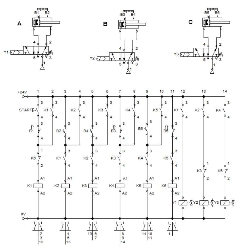
Figure 1: Electro-pneumatic circuit for Bending Device
In Figure 1, there are 3 pneumatic circuit for each cylinder. The circuit are composed of a single solenoid 5/2 way directional control valve, a one-way flow control valve, and a double-acting cylinder. The pneumatic circuit for each cylinder is the same. The sequencing happen in the control circuit for the cylinder. The electrical control circuit six relays that actuates 3 solenoids. A start push button enables the process to commence. Also, there are six sensors that detects the position of the cylinder at any given time so that a correct sequence is achieve. Cylinder A, B and C are monitored by sensor B1, B3, and B5 at retracted position while B2, B4 and B6 at extended position respectively
Figure 2: Start push button is pressed.
For the actuation of cylinder A, relay coil K1 and K2 is activated when sensor B1 and B2 acknowledged the position of cylinder A. Sensor B1 is in series with the start button to ensure that cylinder A is initial retracted while sensor B2 ensures relay K2 is activated when cylinder A is fully extended (clamped the metal in workstation). When start button is pressed, electricity flows across the relay coil K1 and all contact K1 switched from open to closed position at an instance, as shown in Figure 2. Closing K1 at ladder 12 allowed current to energized solenoid Y1. This result to extending the piston rod of cylinder A by actuating the 5/2 way DCV.
Figure 3: K2 is activated.
When the cylinder A extends and activate sensor S2, relay coil K2 is activated and switched relay contact K2 at ladder 13. This leads to electricity flowing through the solenoid Y2. Once solenoid Y2 is energized, cylinder B extends hence the 5/2 way DCV is actuated by solenoid Y2. This is shown in Figure 3. When cylinder hits full extension, it activates sensor B4 at ladder 5.
Figure 3: K3 is activated.
When relay coil K3 is energized, the contact K3 at ladder 13 cuts the electricity to the solenoid Y2. This deactivate the actuation at the 5/2 way DCV and retracts cylinder B. Once cylinder B is retracted, sensor S3 is activated that caused relay coil K4 to activate. When relay K4 is activated, contact K4 at ladder 14 closes and activates solenoid Y3. Solenoid Y3 actuates the 5/2 way DCV to extend cylinder C. Cylinder C extends and activates sensor S6.
Figure 4: K4 is activated.
When sensor S6 is triggered, relay coil K5 is activated and cuts electricity across solenoid Y3 as contact K5 opens. Solenoid Y5 is deactivated which result to retracting of cylinder C. Once cylinder C is fully retracted, relay K5 is activated and cuts the electricity across relay K1. Hence relay K1 is deenergized, cylinder A retracts to initial state. This is shown in Figure 5. The full simulation is shown in Figure 6.
Figure 5: K6 is activated.
Figure 6: Full Simulation.
3. Conclusion
In this blog, we created a circuit that resonates with the operation of a bending device as described earlier. The circuit has 3 cylinders that extends and retracts to bend a metal strip. Cylinder A extends fully and triggers the sensor to actuate the succeeding cylinder. These three cylinders does not extend and retract simultaneously. It is because we latched the cylinder movement in accordance to the sequence of its motion. If these cylinders extends and retracts all together, we can not achieve the bending process. Placing the sensors and relay contacts accordingly to the predefined sequence enables the bending process to succeed. The configuration of a bending device may vary depending on the bend that is needed. The bending device configuration which is presented above is a simple one and is just to show how the cylinders is arranged to bend materials.
4. References
[1] Pneumatic Basic Level. online access
[2] Pneumatic Advanced Level. online access
[3] Electro-pneumatic Basic Level. online access
(Note: All images and diagram in the text are drawn by the author (@juecoree) except those with separate citation.)
If your are Interested in pneumatic and electro-pneumatic system, you can read:
1. Pneumatic Basics: Direct Control
2. Pneumatic Basics: Indirect Control
3. Pneumatic Basics: AND and OR Logic
4. Pneumatic Basics: Memory Circuit and Speed Control
5. Pneumatic Basics: Dependent control
6. Pneumatic Basics: Multiple Actuators
7. Electro-pneumatic Basic: AND and OR Logic
8. Electro-pneumatic Basics: Interlocking, Latching and XOR logic
9. Electro-pneumatic Basics: Distribution of Workpiece
10. Electro-pneumatic Basic: Ejecting a workpiece
11. Electro-pneumatic Basics: Basic Automation
12. Electro-pneumatic Basics: Automation with Counter
12. Electro-pneumatic Basics: Automating with Timer
13. Electro-pneumatic Basics: Cementing Press (Time Dependent Control)
14. Electro-pneumatic Basics: Embossing Device
Posted with STEMGeeks