Electro-pneumatic Basics: Control of Multiple Actuators(Distribution of Workpiece)
1. Introduction
In the previous post, we highlighted interlocking and latching configuration to either isolate or sustain an activation in control circuit. This blog covers on how we correctly placed the latching and interlock to control two actuators by four pushbutton. Our goal is to interpret response and create an equivalent circuit that adheres to it. For this blog, we define the process of distributing a workplace as:
The arriving workpieces are distributed to four conveyors by means of a switching section. Shifting to the required position is initiated by pushbuttons and must be possible in any sequence. Each pushbutton results to the following response:
1. PB1 retains both cylinder in retracted position.
2. PB2 actuates cylinder A but retains cylinder B at retracted position.
3. PB3 extends cylinder by but retracts cylinder A.
4. PB4 extends both cylinders.
2. Circuit and Simulation
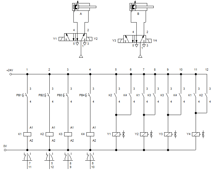
Figure 1: Electro-pneumatic Circuit for Distribution of Workpiece
The control circuit consists of 24V and 0V electrical connection, pushbuttons, relays, and solenoid valves. There are four relays used in the circuit that energizes when a push button is pressed. For condition 1, we placed contact K1 to both solenoid Y2 and Y4 so that it retracts the cylinder or hold it initially at retracted position. Cylinder A extends while cylinder B remain retracted when PB 2 is pressed. With this condition, we connect the relay contacts K2 to Y1 hence Y1 opens up port 4 of the double solenoid, 5/2 way DCV that leads to extending the cylinder. With Y4 in contact with K2, it holds cylinder B at retracted position. Contact K3 is in reverse of K2 wherein K3 is connected to solenoid Y2 and Y3. Contact K4 is connected to Y1 and Y3 so that it extends both cylinder when activated.
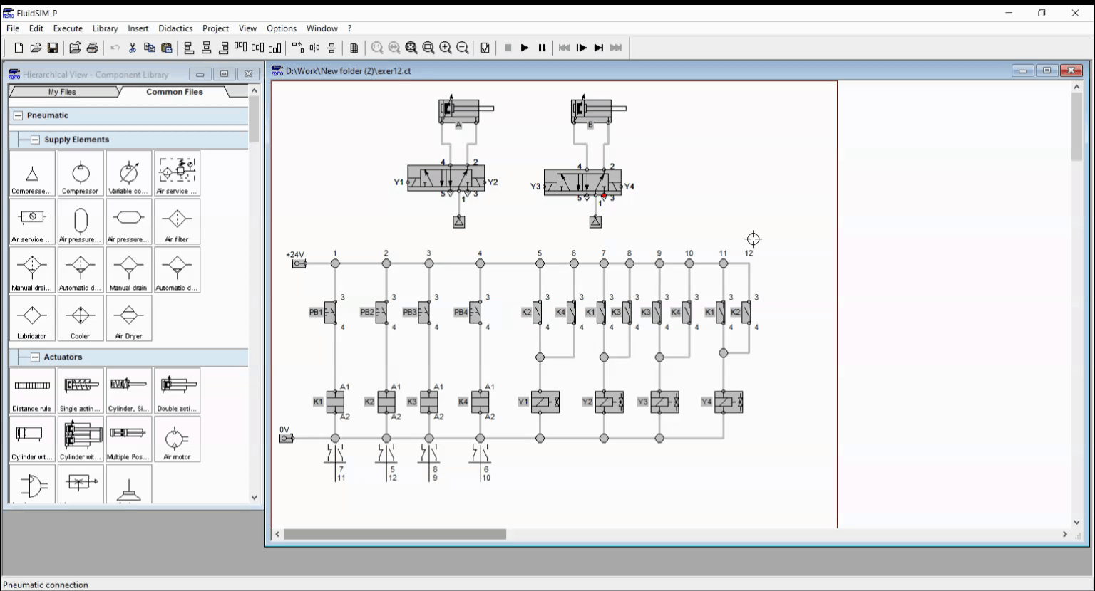
Figure 2: PB2 is pressed.
In the Figure 1, the current flows throughout the solenoid depending on which button was pressed. The cylinder A and B retracts or extend in accordance to the mechanism described earlier. When PB2 is pressed, the relay coil K2 energized which cause the latching contacts K2 to shift from open to close or in reverse. In Figure 2, the current flowed across all closed contact K2 in the control circuit and activated the solenoid Y1 and Y4. Solenoid Y1 shifted the output port of the double-solenoid, 5/2 way valve at cylinder A. The shifting caused the air to flow across the cylinder that leads to extending the piston rod of cylinder A. In contrast, cylinder B was locked at the retracted position when Y4 was actuated.
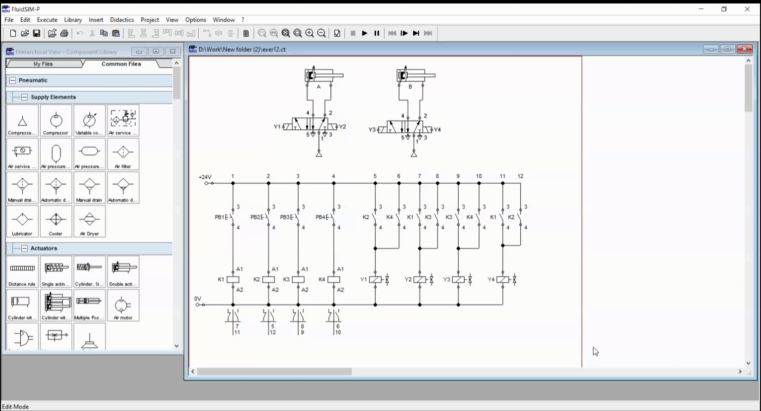
Figure 3: PB3 is pressed.
In Figure 3, the relay coil K3 is activated when PB3 is pressed. The relay contacts K3 closed and allows current to flow to solenoid Y2 and Y3. The solenoid Y2 locked the output of the 5/2 way DCV for cylinder A at port 2. On the other hand, solenoid Y3 actuates 5/2 way DCV that caused the cylinder B to extend.
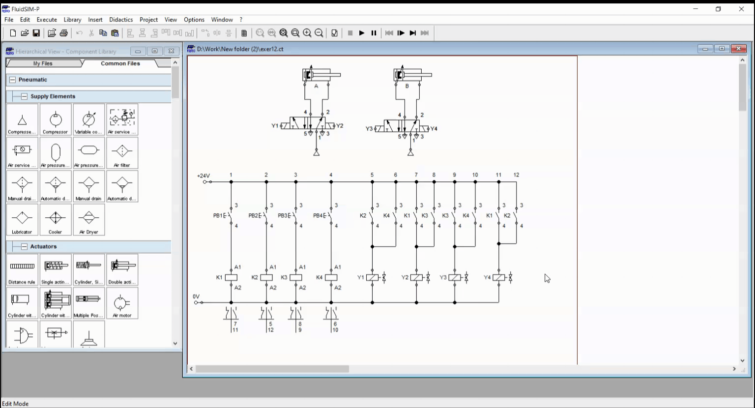
Figure 4: PB4 is pressed.
In Figure 4, both cylinder extends hence the relay coil K4 activates solenoid Y1 and Y3 at the same time. Solenoid Y1 opens port 4 of the double solenoid, 5/2 way DCV of cylinder A that allows air to flow through the cylinder. In the same manner, solenoid Y3 extends cylinder B by opening port 4 of the double-solenoid, 5/2 way DCV at cylinder B.
When the PB1 is pressed at initial state, no movement is observed but if a cylinder already extended, pressing PB1 retracts this cylinder. At initial state, the double solenoid, 5/2 way DCV holds each cylinder at retracted position. This is possible hence the current flows through the relay coil K1 which closes all latched contact K1. This result to energizing solenoid Y2 and Y4 at the same time. Solenoid Y2 and Y4 opened the port 2 of the double solenoid, 5/2 way DCV at each cylinder. This is shown in Figure 5.
Figure 5: PB4 is pressed.
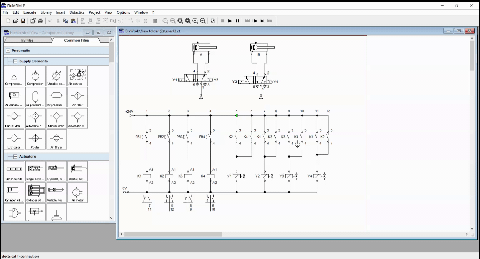
Figure 6: Full simulation.
3. Conclusion
To control multiple actuators, we need to use double solenoid valves at which we can extend or retract the cylinder at will. We correctly assigned the relay contact to its solenoid so that we achieved the condition stated in section 1. The interpretation of the conditional statement is the key in building a correct controller for the given scenario.
4. References
[1] Pneumatic Basic Level. online access
[2] Pneumatic Advanced Level. online access
[3] Electro-pneumatic Basic Level. online access
(Note: All images and diagram in the text are drawn by the author (@juecoree) except those with separate citation.)
If your are Interested in pneumatic and electro-pneumatic system, you can read:
1. Pneumatic Basics: Direct Control
2. Pneumatic Basics: Indirect Control
3. Pneumatic Basics: AND and OR Logic
4. Pneumatic Basics: Memory Circuit and Speed Control
5. Pneumatic Basics: Dependent control
6. Pneumatic Basics: Multiple Actuators
7. Electro-pneumatic Basic: AND and OR Logic
8. Electro-pneumatic Basics: Interlocking, Latching and XOR logic
Posted with STEMGeeks