Electro-Hydraulic Basics: Automating Processes (1 of 3)
1. Introduction
This blog is a 3 part subseries which talks about the different ways to automate a processes in electro-hydraulic system. We cover three automation method in the blog series. First, we create a general circuit that automates a process. Second, automation with time dependent controls. Lastly, automating process using counter. Each method of automation have different scenario or problem to address. For the first problem, we consider the problem defined as
A container of washers is to be dipped in and out of the cleaning bath. The start button initiate the washing. The dipping on the cleaning bath is continuous until stop button is pressed. Once stop button is pressed, the container returns to initial position. By switching off the main valve , the container should not fall into the bath with an impact.
A washing process is continuous once a push button is pressed. The washing process involves extending and retracting the piston of a double-acting hydraulic cylinder. A pair of sensor is in place at retracted and extended length so that we can detect the position at any given instance. When we correctly assign the sensors and relay correctly, the continuous dipping can be achieved. The process is deactivated by pressing a push button. In the next section, the circuit and the simulation is discussed in details.
2. Circuit and Simulation
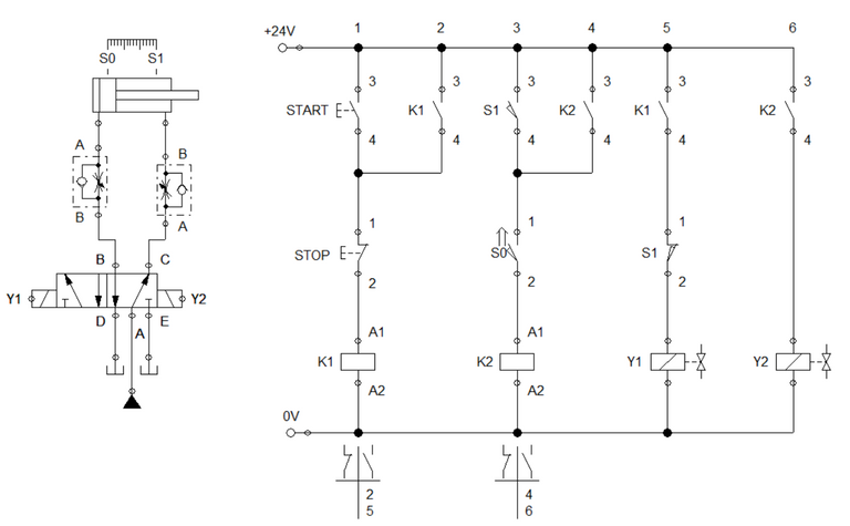
Figure 1: Electro-Hydraulic Circuit
We start creating the hydraulic circuit to drive the double acting cylinder. The hydraulic circuit consist of a double solenoid 5/2 way directional control valve and pair of one-way flow control valve. The double solenoid 5/2 way direction control valve is the main actuating valve for the cylinder while the flow control valve limit the speed of extending and retracting of the cylinder. A sensor is placed at the full retracting and extending length of the cylinder. For the control circuit, we used 2 relay and 2 solenoid. The relay is used to activate the solenoid once the start button is pressed. To automate the process, we used a latching contact for both relay coil so that the relay sustains activation. The configuration is shown in Figure 1.
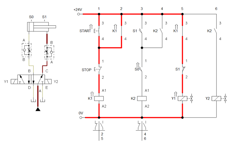
Figure 2: Start button is activated.
When we pressed the start button, electricity flows across relay K1. Once K1 is activated, the relay contact K1 closes to sustain the activation. In step or ladder 5, contact K1 closes to energized the solenoid Y1. Activating solenoid Y1 causes the 5/2 way DCV to open port B. The cylinder extends as fluid pressure passes through port B.
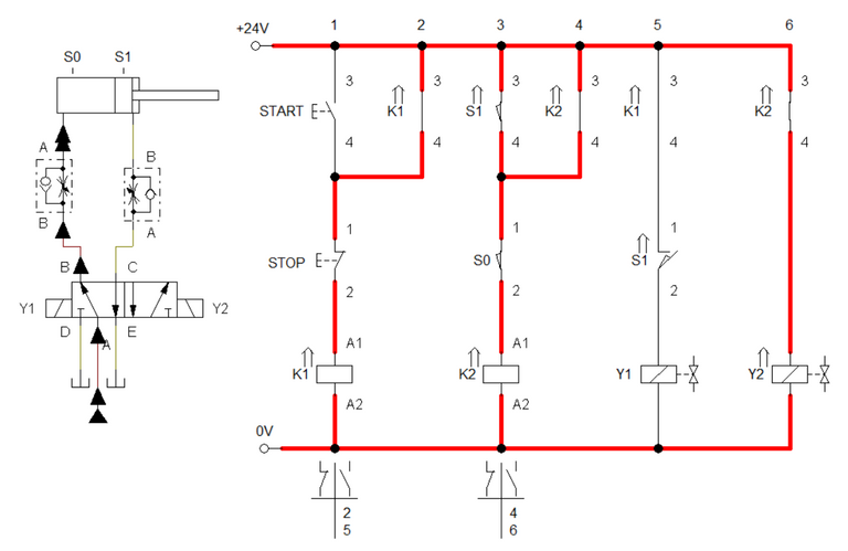
Figure 3. Cylinder fully extended.
Sensor S1 is activated when cylinder reached full extended length. Then, it transmit a signal to close switch S1 in the control circuit. Closing S1 activates relay K2 and closes contact K2 in ladder 6. This results the cylinder to retract to initial position. When the cylinder reaches the initial position, sensor S1 at ladder 5 closes and reactivate the process hence relay K1 is still activated. To stop the process, the stop button must be pressed. The simulation is shown in Figure 4.
3. Conclusion
In this blog, we discussed on how to implement a simple automation using electro-hydraulic. We used a double solenoid control valve as the main control element for the cylinder. The important points to remember in automating a process in electro-hydraulic is to placed the sensor and the relay correctly. The circuit provided in the blog is a general way to automate process.
4. References
[1] Hydraulic Basic Level. online access
[2] Hydraulic Advance Level. online access
[3] Electro-Hydraulic Basic Level. online access
[4] Electro-Hydraulic Advance Level. online access
(Note: All images and diagram in the text are drawn by the author (@juecoree) except those with separate citation.)
If your are interested in pneumatic and hydraulic series, you can read:
Pneumatic and Electro-pneumatic
1. Pneumatic Basics: Direct Control
2. Pneumatic Basics: Indirect Control
3. Pneumatic Basics: AND and OR Logic
4. Pneumatic Basics: Memory Circuit and Speed Control
5. Pneumatic Basics: Dependent control
6. Pneumatic Basics: Multiple Actuators
7. Electro-pneumatic Basic: AND and OR Logic
8. Electro-pneumatic Basics: Interlocking, Latching and XOR logic
9. Electro-pneumatic Basics: Distribution of Workpiece
10. Electro-pneumatic Basic: Ejecting a workpiece
11. Electro-pneumatic Basics: Basic Automation
12. Electro-pneumatic Basics: Automation with Counter
12. Electro-pneumatic Basics: Automating with Timer
13. Electro-pneumatic Basics: Cementing Press (Time Dependent Control)
14. Electro-pneumatic Basics: Embossing Device
15. Electro-pneumatic Basics: Bending Device
16. Electro-pneumatic Basics: Introduction to Logic Module
17. Electro-pneumatic Basics: Automating with Logic Controller
18. Electro-pneumatic Basics: Logic Controller for Multiple Actuators
19.Electro-pneumatic Basics: Time-dependent control with Logic Controller.
Hydraulics and Electro-Hydraulic
20. Hydraulic Basics: Direct Control
21. Hydraulic Basics: Indirect Control
22. Hydraulic Basics: Dual Pressure Value and the AND Logic
23. Hydraulic Basics: Shuttle Valve and the OR Logic
24. Hydraulic Basics: Sequencing Multiple Cylinders (Actuators)
25. Hydraulic Basics: Automating Multiple Cylinders (Actuators)
26. Electro-Hydraulic Basics: Direct and Indirect Control (Part 1 of 2)
27. Electro-Hydraulic Basics: Direct and Indirect Control (Part 2 of 2)
28. Electro-Hydraulic Basics: Two ways in Implementing AND logic
29. Electro-Hydraulic Basics: Two ways in Implementing OR logic
30. Electro-Hydraulic Basics: Circuit with ON and OFF-delay Timer
Posted with STEMGeeks
Congratulations @juecoree! You received a personal badge!
Wait until the end of Power Up Day to find out the size of your Power-Bee.
May the Hive Power be with you!
You can view your badges on your board and compare yourself to others in the Ranking
Check out the last post from @hivebuzz: