Hydraulic Basics: Indirect Control
1. Introduction
Indirect control allows cylinders to be driven by a control valve rather than the main actuating push button. In comparison to direct control, indirect control circuit has an intermediate control valve between the activating button and the actuator. The control valve serves as the final control element in the circuit. The indirect control are usually used in large cylinders that operates at a higher speed. In this blog, we create a circuit that shows the indirect control of hydraulic cylinder (single or double acting). The circuit is based from the given problem or process. The problem is described as:
A double-acting cylinder extends when a button is pressed. Once the button is released, the actuation is deactivated and cylinder returns to initial state. In this problem, assume a large hydraulic cylinder is operated. Additional condition to be fulfilled is the retraction and extending speed is limited to 50% as to the input fluid pressure.
2. Circuit and Simulation
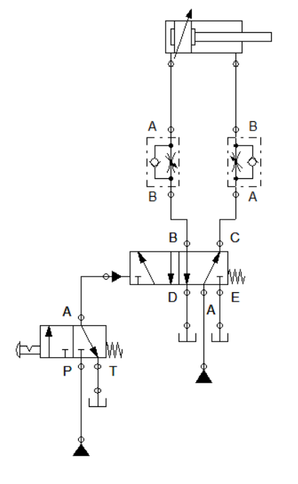
Figure 1: Hydraulic Circuit for Indirect Control
The hydraulic circuit consist of a 3/2 way directional valve with detent switch and spring return, hydraulically actuated 5/2 way directional valve with spring return, a pair of one-way flow control valve and a double-acting cylinder. The circuit configuration is shown in Figure 1. We note that all exhaust port in the circuit is connected to a tank so that no build up of fluids across the components.
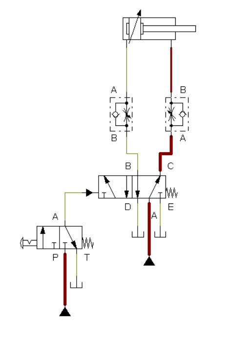
Figure 2: Initial condition
At initial state, the 5/2 way DCV opens port C to make sure the cylinder is fully retracted. This is shown in Figure 2. When the button of the 3/2 way DCV is pressed, the fluid pressure flows across the hydraulic actuating port of the 5/2 way DCV. When the 5/2 way DCV is fully actuated, the valve shifted the opening from port C to B. This yield to fluid pressure to build across the cylinder. This enables the cylinder to extends. This is shown in Figure 3.
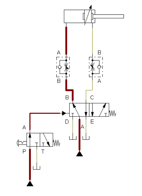
Figure 3: Cylinder extends.
When the button across the 3/2 way DCV is released, the fluid pressure across port B at 5/2 way DCV is cut off. As a result, the cylinder retracts to initial state. The one-way control valve in the circuit limit the fluid pressure to 50% and the cylinder's extending and retracting speed. The 5/2 way directional control valve is the final control element that drives the actuation of the hydraulic cylinder. The 5/2 way DCV shifted the output port in response to the hydraulic actuation signal from the button. The full simulation is shown in Figure 4.
Figure 4: Full Simulation
3. Conclusion
This circuit presented in the previous section is suited for large hydraulic cylinders and cylinders that operates at a high speed. In indirect control, we highlighted the final control element in the circuit. The final control element enables the appropriate fluid pressure to the hydraulic cylinder. In the blog presented how indirect control is configured in hydraulic system.
4. References
[1] Hydraulic Basic Level. online access
[2] Hydraulic Advance Level. online access
(Note: All images and diagram in the text are drawn by the author (@juecoree) except those with separate citation.)
Hello Hive! If your are interested in pneumatic and hydraulic series, you can read:
Pneumatic and Electro-pneumatic
1. Pneumatic Basics: Direct Control
2. Pneumatic Basics: Indirect Control
3. Pneumatic Basics: AND and OR Logic
4. Pneumatic Basics: Memory Circuit and Speed Control
5. Pneumatic Basics: Dependent control
6. Pneumatic Basics: Multiple Actuators
7. Electro-pneumatic Basic: AND and OR Logic
8. Electro-pneumatic Basics: Interlocking, Latching and XOR logic
9. Electro-pneumatic Basics: Distribution of Workpiece
10. Electro-pneumatic Basic: Ejecting a workpiece
11. Electro-pneumatic Basics: Basic Automation
12. Electro-pneumatic Basics: Automation with Counter
12. Electro-pneumatic Basics: Automating with Timer
13. Electro-pneumatic Basics: Cementing Press (Time Dependent Control)
14. Electro-pneumatic Basics: Embossing Device
15. Electro-pneumatic Basics: Bending Device
16. Electro-pneumatic Basics: Introduction to Logic Module
17. Electro-pneumatic Basics: Automating with Logic Controller
18. Electro-pneumatic Basics: Logic Controller for Multiple Actuators
19.Electro-pneumatic Basics: Time-dependent control with Logic Controller.
Hydraulics
20. Hydraulic Basics: Direct Control
Posted with STEMGeeks