Electro-Hydraulic Basics: Circuit with ON and OFF-delay Timer (Time dependent Control)
In this blog, we discussed on integrating time delays in the actuation of the cylinder. Relay timer are usually on-delay or off-delay and can be used interchangeably in any given scenario. The main difference between the two is the activation of the timer mechanism. For the on-delay, the timer activates first before the closing or opening of contacts happen while for off-delay, the contacts activate first before the timer starts. In this blog, we used a simple scenario or problem to present the used of timer and the time-dependent control. The problem is described as
The cementing press activates by pressing a button that controls the forward stroke. When the piston rod reached the full extended length, the component is pressed for 10 seconds. After time expires, the piston rod retracts automatically to initial position. It is specified that even the push button is still pressed, the rod retracts after 10 seconds. The process renews after one process cycle and the cylinder is fully retracted.
The problem clearly specify that the retraction is after 10 seconds. We can used either a on or off-delay timer relay. In this blog, we provide two ways to achieve the conditions in the problem. The first method is to employ an on-delay timer while the other is to used off-delay. In the next section, the circuit and process explanation is detailed.
2. Circuit and Simulation
Electro-Hydraulic Circuit with On-delay Timer
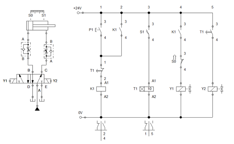
Similar to the previous blogs, the pneumatic circuit is configured with a pair of one-way flow control valve and a double solenoid 5/2 way directional valve. For the control circuit, we integrate what we have learned so far in the previous blogs. At ladder 1, a push button is in parallel to a relay contact K1 which enables the relay K1 activation to sustain. This connection is in series with timer contact T1 and the relay K1. The timer contact serves as the isolating mechanism that cuts off electricity to relay k1 when process is done. in the next step or ladder, the sensor S1 actuates the timer relay T1. The sensor S1 only transmit activation signal to the timer when the cylinder reached the full extended length. Solenoid Y1 is driven by K1 and S0 which ensures the cylinder to extend only when cylinder is at initial state. The circuit configuration is shown in Figure 1.
Figure 2: Simulation
When the push button is pressed, the electricity flows through the relay coil K1 and energized it. The latching contact across P1 sustain the relay activation and at the same time, activates the solenoid Y1. This extends the cylinder. Once cylinder reached full extended length, the sensor S1 activates the relay timer. After 10 seconds, the relay contacts T1 switches from open to close or in reverse. This result to activation of Y2 and deactivation of relay K1. The cylinder retracts as solenoid Y2 is activated. The simulation is shown in Figure 2.
Electro-Hydraulic Circuit with Off-Delay Timer
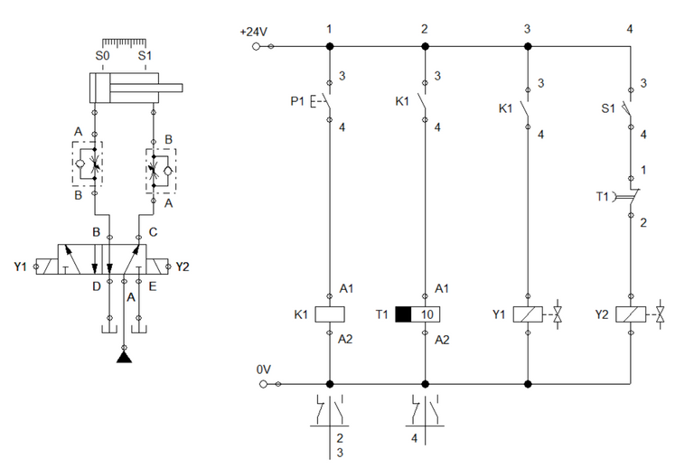
For the off-delay, a push button activate a relay K1 while relay K1 activates the timer T1. Once K1 is activated, the cylinder start to extend and reached full extended length in no time. As the timer lapse, the relay timer activate the latching contacts T1. This result to solenoid Y2 to activate. Solenoid Y2 retracts the cylinder. We take note that the retraction should have both the sensor S1 and timer contact T1 activated before solenoid is energized. The circuit is shown in Figure 3 while the simulation is shown in Figure 4.
Figure 4. Simulation for Off-delay
3. Conclusion
In this blog, we discussed on how to implement the time-dependent control in electro-hydraulic. Also, we highlighted two method to implement it. The first method used on-delay timer which activates the actuating mechanism after the time expires. In contrast, the second method used an off-delay timer which enables actuation to commence before cutting it off.
4. References
[1] Hydraulic Basic Level. online access
[2] Hydraulic Advance Level. online access
[3] Electro-Hydraulic Basic Level. online access
[4] Electro-Hydraulic Advance Level. online access
(Note: All images and diagram in the text are drawn by the author (@juecoree) except those with separate citation.)
If your are interested in pneumatic and hydraulic series, you can read:
Pneumatic and Electro-pneumatic
1. Pneumatic Basics: Direct Control
2. Pneumatic Basics: Indirect Control
3. Pneumatic Basics: AND and OR Logic
4. Pneumatic Basics: Memory Circuit and Speed Control
5. Pneumatic Basics: Dependent control
6. Pneumatic Basics: Multiple Actuators
7. Electro-pneumatic Basic: AND and OR Logic
8. Electro-pneumatic Basics: Interlocking, Latching and XOR logic
9. Electro-pneumatic Basics: Distribution of Workpiece
10. Electro-pneumatic Basic: Ejecting a workpiece
11. Electro-pneumatic Basics: Basic Automation
12. Electro-pneumatic Basics: Automation with Counter
12. Electro-pneumatic Basics: Automating with Timer
13. Electro-pneumatic Basics: Cementing Press (Time Dependent Control)
14. Electro-pneumatic Basics: Embossing Device
15. Electro-pneumatic Basics: Bending Device
16. Electro-pneumatic Basics: Introduction to Logic Module
17. Electro-pneumatic Basics: Automating with Logic Controller
18. Electro-pneumatic Basics: Logic Controller for Multiple Actuators
19.Electro-pneumatic Basics: Time-dependent control with Logic Controller.
Hydraulics and Electro-Hydraulic
20. Hydraulic Basics: Direct Control
21. Hydraulic Basics: Indirect Control
22. Hydraulic Basics: Dual Pressure Value and the AND Logic
23. Hydraulic Basics: Shuttle Valve and the OR Logic
24. Hydraulic Basics: Sequencing Multiple Cylinders (Actuators)
25. Hydraulic Basics: Automating Multiple Cylinders (Actuators)
26. Electro-Hydraulic Basics: Direct and Indirect Control (Part 1 of 2)
27. Electro-Hydraulic Basics: Direct and Indirect Control (Part 2 of 2)
28. Electro-Hydraulic Basics: Two ways in Implementing AND logic
29. Electro-Hydraulic Basics: Two ways in Implementing OR logic
Posted with STEMGeeks