Electro-Hydraulic Basics: Two ways in Implementing AND logic
1. Introduction
In a pure hydraulic circuit, we used the dual pressure valve to be able to control the double-acting cylinder which emulates an AND logic. In this blog, we implement the AND logic in electro-hydraulic circuit. We use a problem or scenario to be our basis in creating the circuit. The problem is described as
A double acting hydraulic cylinder is to extends only if a work piece is inserted in the retainer, a guard has been lowered and the operator presses the push button valve. Upon release of the push button or if the guard is no longer in its lower position, the cylinder is to retract to initial position. The motion should be limited to 50%.
As stated in the problem, the cylinder is extended or retracted by two push button. Releasing one button retracts the cylinder to initial position. There are two ways to implement the automatic retraction of the cylinder. First we used a control valve with spring return. The other is to set a sensor (limit switch) to detect the process is done. In the next section, the circuit is discussed in detail.
2. Circuit and Simulation
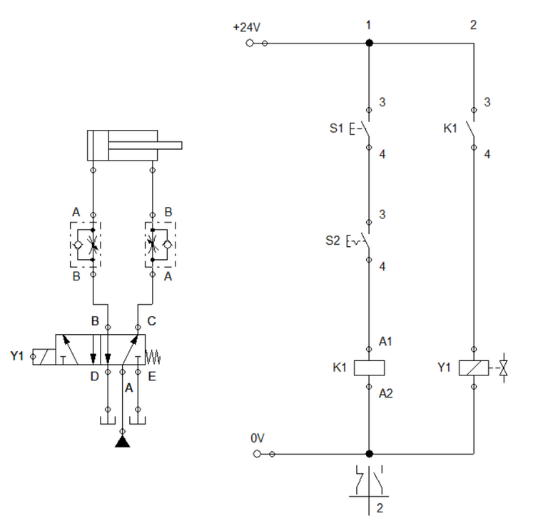
FIgure 1: Electro-Hydraulic Circuit for AND Logic (without sensors)
The pneumatic circuit used a single solenoid 5/2 way directional control valve with spring return to actuate the cylinder. The control mechanism is provided by two push button, a relay and a solenoid. In this circuit, we employ indirect control hence we used a relay to energized the solenoid Y1 which drives the 5/2 way DCV. The problem with this circuit is inability to complete a full retraction once instantaneously released the button. This is a simplistic way to implement the AND logic. The simulation is shown in Figure 2.
Figure 2: Simulation for Figure 1
To address the problem in Figure 1, we integrate sensors to detect the given position of the cylinder at any given instance. This ensures that cylinder fully retracts before the repressing the button or after releasing the button. The circuit consist of a double-acting cylinder that is driven by a double solenoid 5/2 way directional control valve. We used the double solenoid control valve so that we have the flexibility in controlling both the extending and retracting of the cylinder.
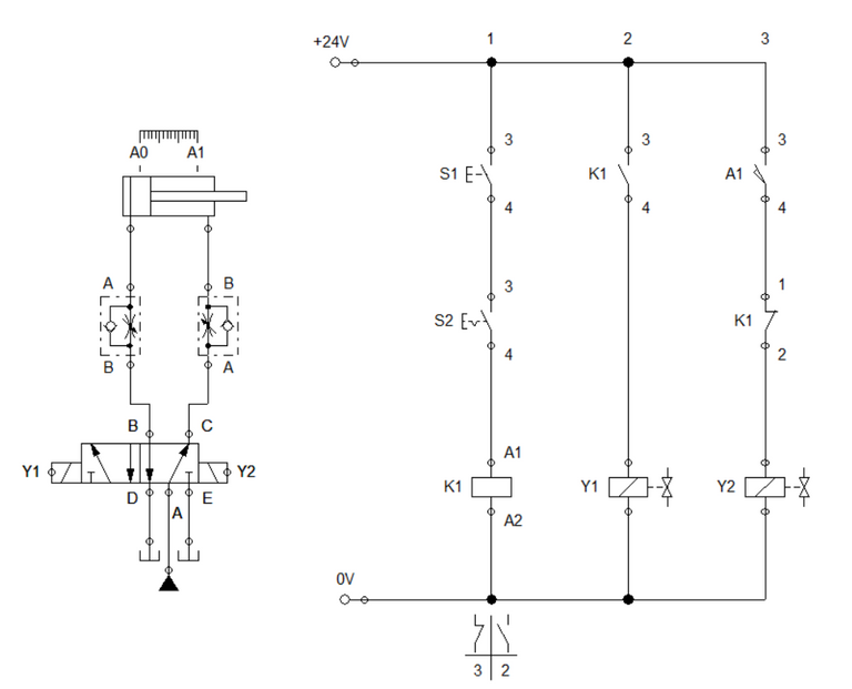
Figure 3: Electro-Hydraulic Circuit for AND Logic (modified, with sensor)
For the controller in Figure 3, we used two set of solenoid to drive the 5/2 way DCV. Solenoid Y1 enables cylinder to extend while Y2 retracts it. The AND logic is utilized in ladder 1 and 3. The configuration of buttons in ladder 1 emulates and AND logic while the sensor A1 and relay K1 is in an AND logic also. When the pair of button is actuated, relay K1 is energized which activates contacts K1 and and solenoid Y1. This extends the cylinder. Once the cylinder is fully extended and sensor A1 detects it, the solenoid Y2 is activated to retract the cylinder except the relay K1 is engaged. The fluid and electrical flow is shown in Figure 4 while the simulation in Figure 5.
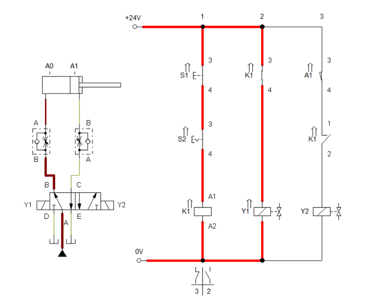
Figure 4: Push button is activated.
Figure 5. Simulation
3. Conclusion
In this blog, we discussed two ways to implement the AND logic in electro-hydraulic. The first method relies on simplistic approach where there is an issue with regards to the full extending. This issue is due to quickly releasing the button that deactivates the electrical flow through the solenoid Y1. To address the problem, we integrate a sensors to serve as the memory circuit so that when we quickly released the push button, the extending mechanism is complied.
4. References
[1] Hydraulic Basic Level. online access
[2] Hydraulic Advance Level. online access
[3] Electro-Hydraulic Basic Level. online access
[4] Electro-Hydraulic Advance Level. online access
(Note: All images and diagram in the text are drawn by the author (@juecoree) except those with separate citation.)
If your are interested in pneumatic and hydraulic series, you can read:
Pneumatic and Electro-pneumatic
1. Pneumatic Basics: Direct Control
2. Pneumatic Basics: Indirect Control
3. Pneumatic Basics: AND and OR Logic
4. Pneumatic Basics: Memory Circuit and Speed Control
5. Pneumatic Basics: Dependent control
6. Pneumatic Basics: Multiple Actuators
7. Electro-pneumatic Basic: AND and OR Logic
8. Electro-pneumatic Basics: Interlocking, Latching and XOR logic
9. Electro-pneumatic Basics: Distribution of Workpiece
10. Electro-pneumatic Basic: Ejecting a workpiece
11. Electro-pneumatic Basics: Basic Automation
12. Electro-pneumatic Basics: Automation with Counter
12. Electro-pneumatic Basics: Automating with Timer
13. Electro-pneumatic Basics: Cementing Press (Time Dependent Control)
14. Electro-pneumatic Basics: Embossing Device
15. Electro-pneumatic Basics: Bending Device
16. Electro-pneumatic Basics: Introduction to Logic Module
17. Electro-pneumatic Basics: Automating with Logic Controller
18. Electro-pneumatic Basics: Logic Controller for Multiple Actuators
19.Electro-pneumatic Basics: Time-dependent control with Logic Controller.
Hydraulics and Electro-Hydraulic
20. Hydraulic Basics: Direct Control
21. Hydraulic Basics: Indirect Control
22. Hydraulic Basics: Dual Pressure Value and the AND Logic
23. Hydraulic Basics: Shuttle Valve and the OR Logic
24. Hydraulic Basics: Sequencing Multiple Cylinders (Actuators)
25. Hydraulic Basics: Automating Multiple Cylinders (Actuators)
26. Electro-Hydraulic Basics: Direct and Indirect Control (Part 1 of 2)
27. Electro-Hydraulic Basics: Direct and Indirect Control (Part 2 of 2)
Posted with STEMGeeks