Electro-pneumatic Basics: Logic Controller for Multiple Actuators
1. Introduction
In a previous blog , we automated a process using a logic controller. In this blog, we elaborate more on the logic controllers and create a circuit that controls multiple actuators. The problem or process to be simulated is for the embossing device, which is described as
Plastic parts are manually placed in a holder by which it is . A pneumatic cylinder pushes the holder under an embossing cylinder 2.0 (B). This cylinder embosses names in the plastic. After embossing, the cylinder 2.0 (B) returns immediately to its initial position. Only then does cylinder 1.0 (A) return.
In the process description, the cylinder A extends and hold the plastic part in placed prior to embossing. A pair of sensor is placed at each cylinder to coordinate its motion. This enables us to extend the cylinder B after cylinder A is actuated. In the next section, we implement and discussed the circuit for the process at hand.
2. Circuit and Simulation
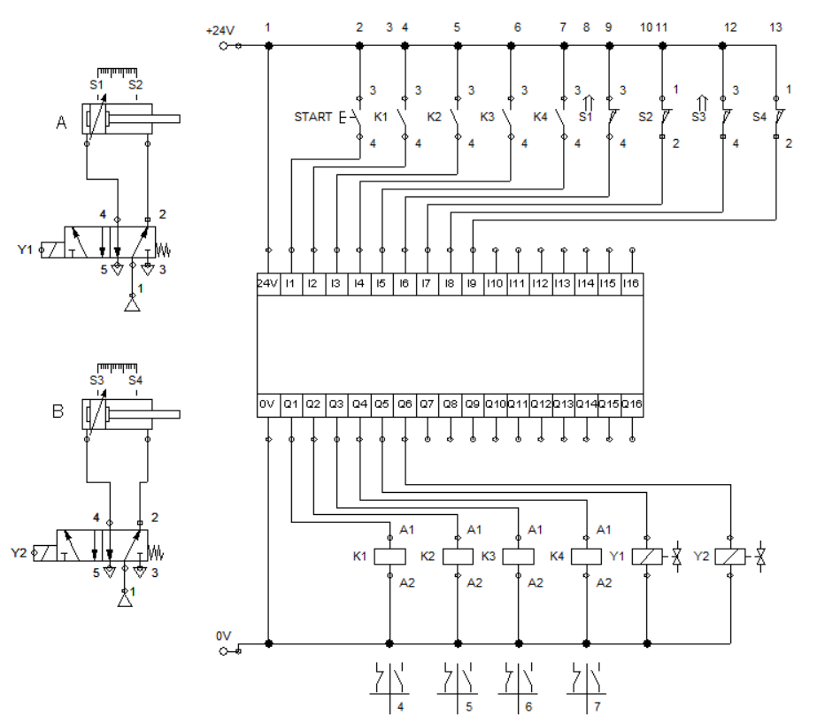
Figure 1: Embossing Device using Logic Module
We start with wiring the pneumatic circuit, shown in Figure 1. Each cylinder is drive by a single solenoid 5/2 way directional valve. Sensors are placed at the initial and extended position of each cylinder. We set up the input devices to the logic module. The inputs are start push buttons, three set of relay contacts and sensors while the output is feed to a relay coil and solenoid. Relay K1 and K2 established established the activation of the solenoids Y1 and Y2 while relay K3 and K4 retracts the cylinder after they hit the sensors S and S4 respectively. deactivates K1. Each cylinder are driven by solenoid Y1 and Y2. The input and output set up is shown in Figure 1.
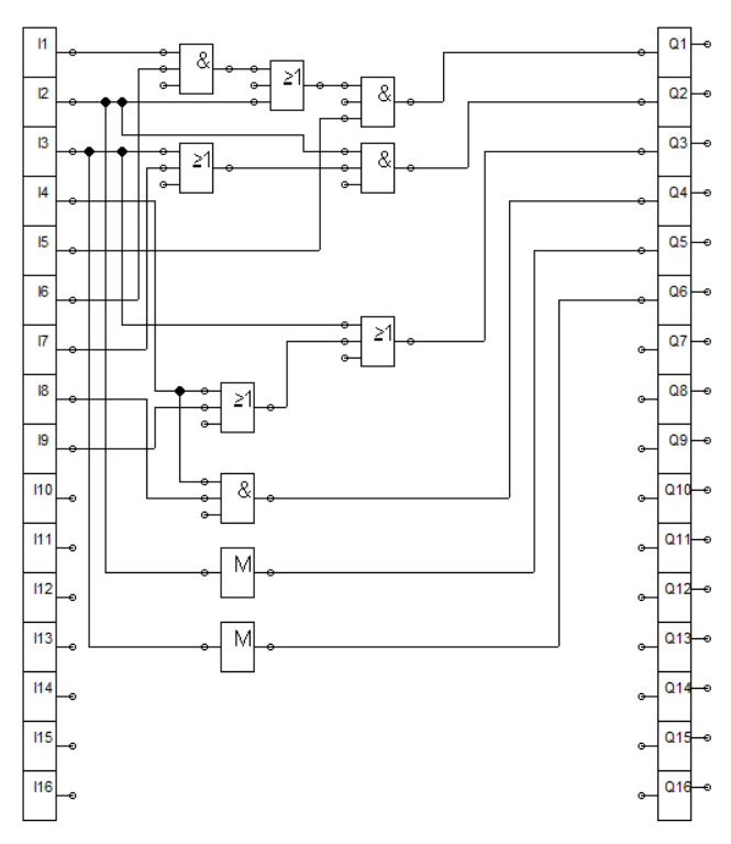
Figure 2: Logic
For activating K1, we connect the start button and sensor S1 to an AND gate. AND gate output is connected to OR gate together with contact K1. The combination is wired together with contact K4 using an AND gate. This drives the relay coil K1 (connected across Q1. The logic simulation is shown in Figure 2.
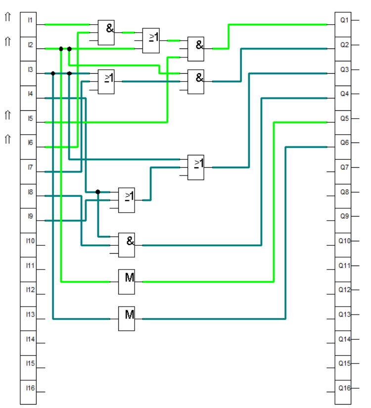
Figure 2: K1 activation
For activating K2, sensor S2 and contact K2 is connected thru a OR gate and the result is feed to an AND gate together with contact K1. To activate K3, we sired to the input of an OR gate both sensor S4 and contact K3. After connect it to an AND gate with contact K2. For K4, We simply connect an AND gate with sensor S3 and contact K3 as the input. The logic simulations are shown in Figure 3.
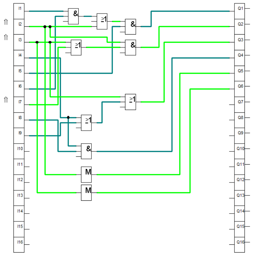
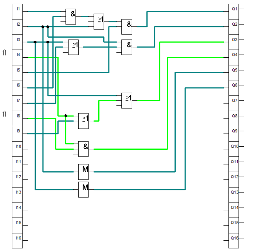
Figure 3: Relay and solenoid activation.
Hence we already configured the logic controller, It is now time to simulate the circuit. When we pressed the start button, the high signal is feed at I1 of the logic module. This result to activation of relay coil K1. Once K1 is activated, contact K1 closes and activate relay coil K2. The process continues until all steps are attained. The full simulation is shown in Figure 4.
Figure 4: Full Simulation
3. Conclusion
We created a circuit that enables logic controller to control multiple actuators, shown in Figure 1. We accomplished the task by combining different logical functions. We placed the sensors correctly so that circuit response mimics the problem or scenario. Overlapping of signal causes the circuit to not run or run incorrectly to what was desired.
4. References
[1] Pneumatic Basic Level. online access
[2] Pneumatic Advanced Level. online access
[3] Electro-pneumatic Basic Level. online access
[4] Electro-pneumatic Advance Level. online access
[5] Programmable Logic Controller Basic Level. online access
(Note: All images and diagram in the text are drawn by the author (@juecoree) except those with separate citation.)
If your are Interested in pneumatic and electro-pneumatic system, you can read:
1. Pneumatic Basics: Direct Control
2. Pneumatic Basics: Indirect Control
3. Pneumatic Basics: AND and OR Logic
4. Pneumatic Basics: Memory Circuit and Speed Control
5. Pneumatic Basics: Dependent control
6. Pneumatic Basics: Multiple Actuators
7. Electro-pneumatic Basic: AND and OR Logic
8. Electro-pneumatic Basics: Interlocking, Latching and XOR logic
9. Electro-pneumatic Basics: Distribution of Workpiece
10. Electro-pneumatic Basic: Ejecting a workpiece
11. Electro-pneumatic Basics: Basic Automation
12. Electro-pneumatic Basics: Automation with Counter
12. Electro-pneumatic Basics: Automating with Timer
13. Electro-pneumatic Basics: Cementing Press (Time Dependent Control)
14. Electro-pneumatic Basics: Embossing Device
15. Electro-pneumatic Basics: Bending Device
16. Electro-pneumatic Basics: Introduction to Logic Module
17. Electro-pneumatic Basics: Automating with Logic Controller
Posted with STEMGeeks
Congratulations @juecoree! You have completed the following achievement on the Hive blockchain and have been rewarded with new badge(s) :
You can view your badges on your board and compare yourself to others in the Ranking
If you no longer want to receive notifications, reply to this comment with the word
STOP