Electro-pneumatic Basics: Introduction to Logic Module (Programmable Logic Controller)
1. Introduction
In the previous blogs, we implement a solution to a given problem or scenario in either pneumatic or electro-pneumatic system. In this blog, we explore programmable logic controllers (modules) to achieve the process as described in a given scenario or a problem. We used the some scenarios in the previous blog and come up with a logic controller implementation. Also, we explain the basic logical functions (gates) to be used in achieving the processes in the problem.
2. The Logic Gates
In this section, we explain the basic logical gates that can be used in our logic modules. There are at least eight logic gates to be discussed in this section. Also, we elaborate on how we can implement the logic gates in our logic modules. We start with the buffer. The buffer is a logic gate that has the same input and output. Technically, the buffer is not useful with regards to application. It is like a channel and never changes the value of the signal. The NOT gate inverts the input. For example, pressing a button retracts an extended cylinder and when not pressed, the system returns to extended position. The truth table for buffer and NOT gates are shown in Table 1 and Table 2.
| A | B |
|---|---|
| 0 | 0 |
| 1 | 1 |
| A | B |
|---|---|
| 0 | 1 |
| 1 | 0 |
The AND gate allows output to have a high (or 1) value when both input are the same. In case one of the input becomes low (or 0), the output is low (or 0). In logic controls, we can designate it as two push button assigned to control the actuation of the cylinder. Pressing one button does not extends the cylinder. In contrast, NAND gate set the output to high value when either of the input becomes a low value. The truth tables shows the AND and NAND logic. In the truth table, A and B are input while C is the output.
| A | B | C |
|---|---|---|
| 0 | 0 | 0 |
| 0 | 1 | 0 |
| 1 | 0 | 0 |
| 1 | 1 | 1 |
| A | B | C |
|---|---|---|
| 0 | 0 | 1 |
| 0 | 1 | 1 |
| 1 | 0 | 1 |
| 1 | 1 | 0 |
The OR logic results to a high value (1) when either of the input becomes a high value (1). To elaborate, a cylinder with two push button controls can be actuated by either one or both push button is pressed. In contrast, NOR logic reverses the operation of an OR gate. When both push button is not pressed, the cylinder extend. The truth table for both logic gates are shown below.
| A | B | C |
|---|---|---|
| 0 | 0 | 0 |
| 0 | 1 | 1 |
| 1 | 0 | 1 |
| 1 | 1 | 1 |
| A | B | C |
|---|---|---|
| 0 | 0 | 1 |
| 0 | 1 | 0 |
| 1 | 0 | 0 |
| 1 | 1 | 0 |
The XOR logic (exclusive OR) specifically set the output to high when the pair of input is not equal but the output is low when the input are the same. In contrast, XNOR logic results to a high value when the input are the same. The XOR and XNOR logic response to a pair of input is listed in the Table below.
| A | B | C |
|---|---|---|
| 0 | 0 | 0 |
| 0 | 1 | 1 |
| 1 | 0 | 1 |
| 1 | 1 | 0 |
| A | B | C |
|---|---|---|
| 0 | 0 | 1 |
| 0 | 1 | 0 |
| 1 | 0 | 0 |
| 1 | 1 | 1 |
3. Circuit and Simulation
In this blog, we create a circuit for punching devices using the logic module in FluidSim. In the previous blog, we talked about the pure electro-pneumatic implementation for the punching device. The process involves in the punching device is described as:
A notch is to punched in the workpiece by a pneumatic cylinder. The workpiece is fed from any one of three work stations. The punching operation is to be triggered when 2 sensors emit a signal. The signaling elements a, b and c are installed for sensing. The cylinder returns to its retracted position when the part is pulled out of the device.
The control circuit for the punching device allows a workpiece to be punch by a pneumatic cylinder when 2 sensors are activated. We note that when three sensor is activated at once, the pneumatic cylinder remains retracted. We used a combination of NOT, AND, and OR logic gates to achieve what was asked in the problem.
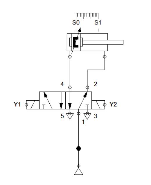
Figure 1: Pneumatic Circuit for the Punching Device
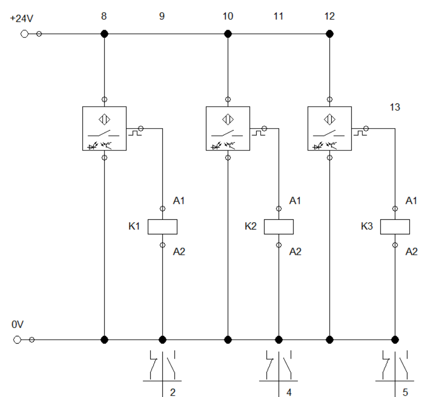
Figure 2: Sensor circuit for the Punching Device
We start with the pneumatic circuit. The cylinder can be actuated by means of a double solenoid 5/2 way directional valve. For the sensor circuit, we configure three optical sensors that are assigned to relay K1, K2 and K3. The pneumatic circuit is shown in Figure 1 while sensor circuit is in Figure 2.
Next, we configure the logical functions in our logic module. In reality, the logic module is a programmable logic controller where you can load codes (logical functions) to achieve the process requirement. In Figure 3, the controller is built by interconnecting the NOT, AND and OR gate. The AND gate is used to interpret that two sensor should be activated at the same time for the cylinder to extend. The OR gate is used to check the combinations between any given pair of sensor is activated. The NOT gate allow us to isolate the system when 3 sensors are simultaneously activated. The connection is shown in Figure 3.
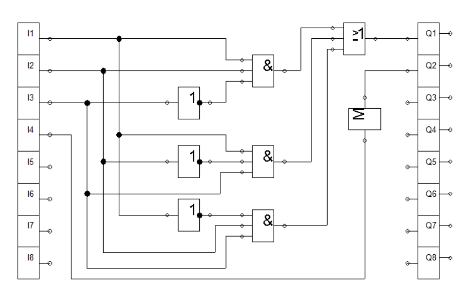
Figure 3: Logic Module
Figure 4: Logic Module Simulation
In the logic module, two high value at the input results to a high (1) value at the output while activating three sensor yield to a low (0) output. This is shown in Figure 4. Hence the logic module's input ports are connected to the relay K1, K2, and K3, a signal is passed to the input of the logic module which caused it to have an output value. The control circuit is shown in Figure 5.
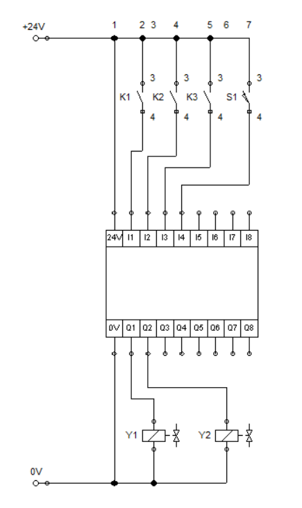
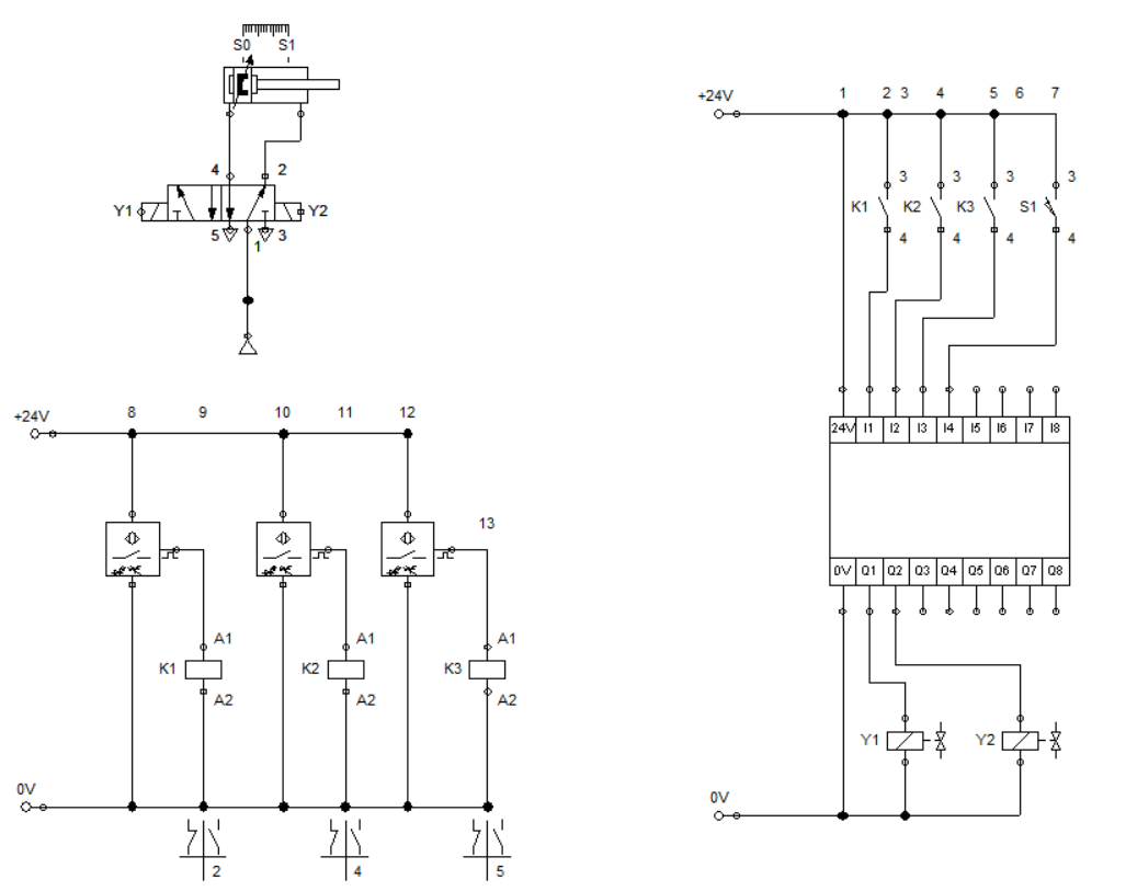
Figure 5: Control circuit for Punching Device
When two sensors are activated, current flows across the respective relay coil that caused the contacts at the control circuit to closed. This transmit a high (1) input to the logic controller (module). The input signal is processed and an output signal is passed to the solenoid Y1 and Y2. Solenoid Y1 enable the cylinder to extend when two sensors are activated while Y2 retracts the cylinder after it fully extend. The simulation is shown in Figure 7.
Figure 6: Full Circuit
Figure 7: Full Simulation
4. Conclusion
In this blog, we discussed the basic logic gates and apply it to our logic controllers (module). We created an equivalent circuit for the punching device using the programmable logic controller (module). The logic module can be configured in different ways by combining the basic logic gates.
5. References
[1] Pneumatic Basic Level. online access
[2] Pneumatic Advanced Level. online access
[3] Electro-pneumatic Basic Level. online access
[4] Electro-pneumatic Advance Level. online access
[5] Programmable Logic Controller Basic Level. online access
(Note: All images and diagram in the text are drawn by the author (@juecoree) except those with separate citation.)
If your are Interested in pneumatic and electro-pneumatic system, you can read:
1. Pneumatic Basics: Direct Control
2. Pneumatic Basics: Indirect Control
3. Pneumatic Basics: AND and OR Logic
4. Pneumatic Basics: Memory Circuit and Speed Control
5. Pneumatic Basics: Dependent control
6. Pneumatic Basics: Multiple Actuators
7. Electro-pneumatic Basic: AND and OR Logic
8. Electro-pneumatic Basics: Interlocking, Latching and XOR logic
9. Electro-pneumatic Basics: Distribution of Workpiece
10. Electro-pneumatic Basic: Ejecting a workpiece
11. Electro-pneumatic Basics: Basic Automation
12. Electro-pneumatic Basics: Automation with Counter
12. Electro-pneumatic Basics: Automating with Timer
13. Electro-pneumatic Basics: Cementing Press (Time Dependent Control)
14. Electro-pneumatic Basics: Embossing Device
15. Electro-pneumatic Basics: Bending Device
5. References
Posted with STEMGeeks