Hydraulic Basics: Automating Multiple Cylinders (Actuators)
1. Introduction
In the previous blog, we discussed on how to correctly placed the sensor to achieve the desired motion sequence of multiple actuators. In this blog, we elevate the discussion and create a hydraulic circuit that automates a process (motion sequence). Similar to the previous blogs, we used a scenario or a problem as the basis for the circuit to be discussed. For this blog, the problem is described as
A box in a vertical stack is to be stamped with a sticker. A cylinder A pushed the boxes out from the stack and Cylinder B stamps the sticker to the box. Cylinder A retracts at after the box is already stamp with a sticker. The process is continuous once activated by pressing a button and can be deactivated by pressing a stop button. To confirm the cylinder position at any given time, a pair of limit switch is placed in each cylinder.
The problem needs two hydraulic cylinders to perform the pushing of boxes from a vertical stack and the stamping of sticker on the box. We can expect to used four sensors in our hydraulic circuit that acknowledges the position of the cylinder at any given time. The motion sequence is A+, B+, A-, B- and repeat (see previous blog for + or - notation). A button is necessary to activate and deactivate the process. In the next section, the hydraulic circuit is discussed ion details.
2. Circuit and Simulation

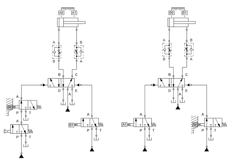
Figure 1: Hydraulic Circuit For Basic Automation
To automate the process of extending and retracting of two cylinders, we set four 3/2 way directional valve that is activated by the sensor (limit switches). Similar to the circuit presented in the previous blog, each cylinder is controlled by a hydraulically actuated 5/2 way directional valve and its speed is limited by a pair of one-way flow control valve. We can sequence the motion of the cylinders by attaching the sensors of cylinder B to cylinder A while cylinder A's sensor at cylinder B. All the 3/2 way DCV used in the circuit are normally open. A 3/2 way DCV with detent switch is placed in cylinder A to activate and deactivate the process. The wiring connection is shown in Figure 1.
The sensors A0, A1, B0, and B1 is linked to the 3/2 way valves in accordance to the motion sequence define in the problem. The placement of the sensors are shown in Figure 1. Sensor B0 at cylinder A enables the cylinder to extend when the button is pressed and retracts when cylinder B returns to retracted position. Sensor B1 activates the retracting mechanism for cylinder A as cylinder B reaches full extension. This configuration allows the A+ and A- sequence to activate.

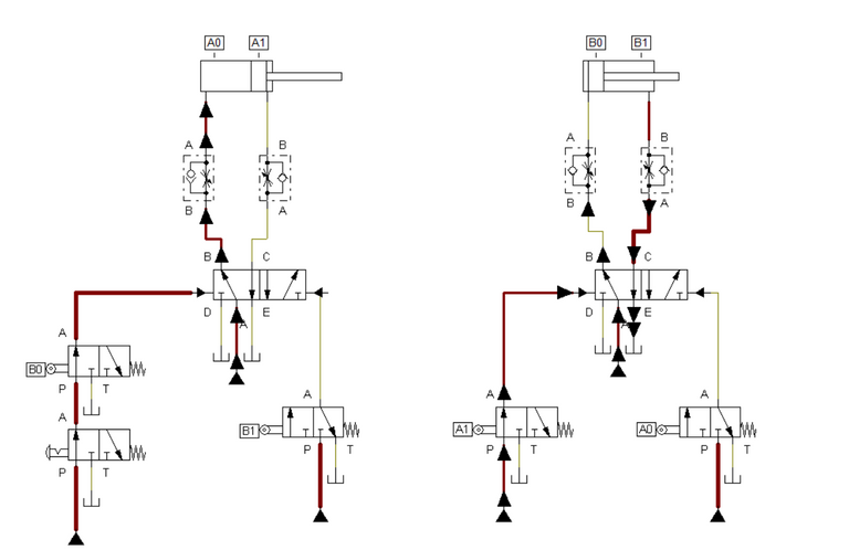
Figure 2: Cylinder A extends.
For cylinder B, A0 is placed at retracting motion of cylinder B so that cylinder B retracts after cylinder A. This enables A- to activate. On the other hand, A1 is linked to the extending motion of the cylinder B and enables the motion sequence B+. This is to assure that cylinder B extends after cylinder A fully extended. For the process to be continuous, B0 should be placed correctly in the circuit hence it restart the process as long as the button is engaged. This placement of sensors enables A+, B+, A-, B- and repeat to be accomplished.

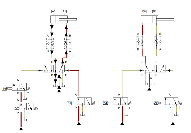
Figure 3: Cylinder B extends.
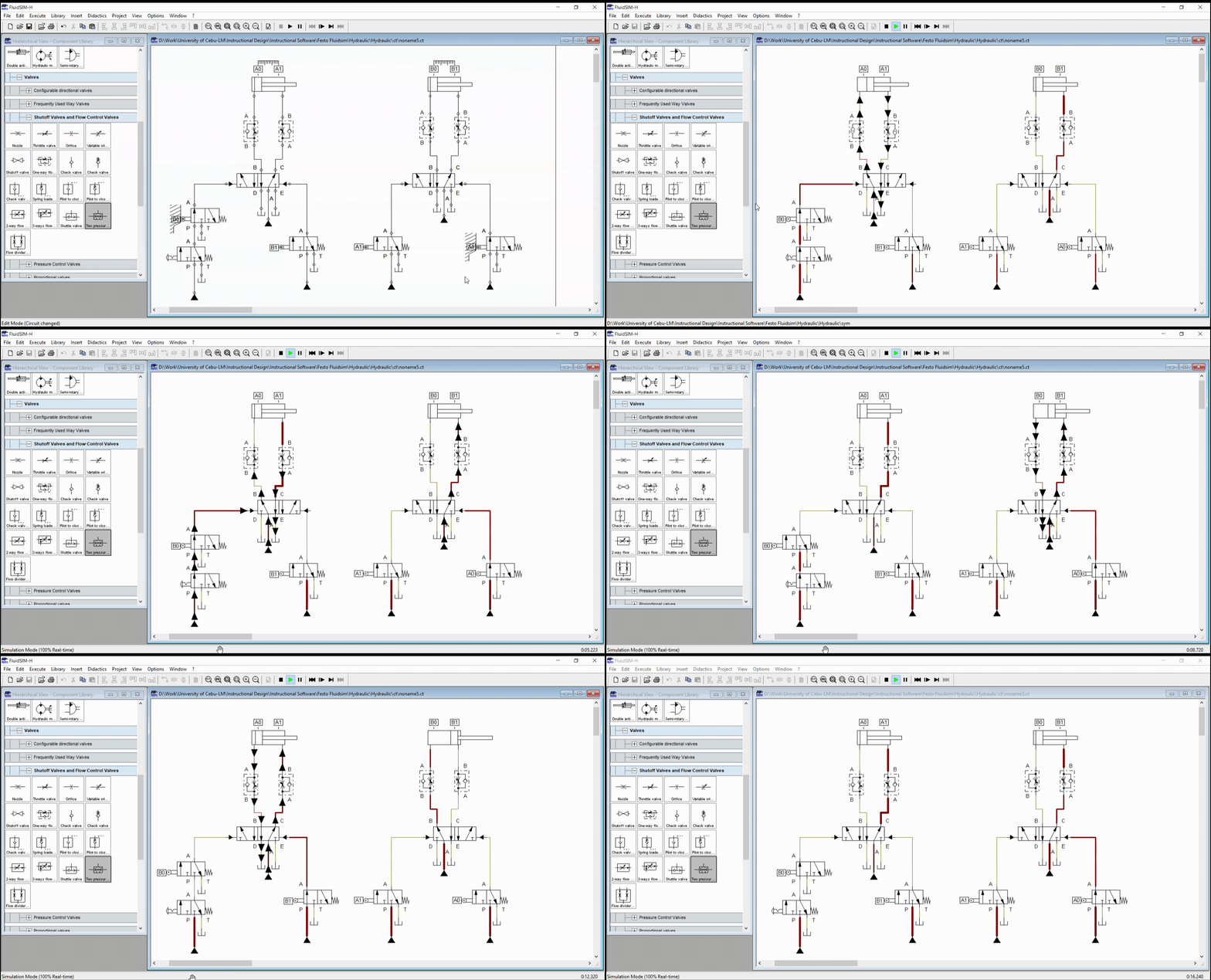
Cylinder A extends when the detent switch is pressed,. This enables the opening of port B of 5/2 way DCV for cylinder A. Once cylinder A extends and reaches sensor A1, sensor A1 activates port B of the 5/2 way DCV for cylinder B. This caused cylinder B to activate and extends. Once cylinder B extends, the actuation at 3/2 way DCV with sensor B0 is cut. This enables cylinder A to retract and return to initial state. When cylinder B reaches sensor B1, sensor B1 retracts cylinder A and cuts activation at 3/2 way DCV with sensor A1. This yield to cylinder B returning to initial state. A fully retracted cylinder B reactivate sensor B0 and the process repeats until detent switch (button) is deactivated. The animated simulation is shown in Figure 4.

Figure 4: Full Simulation
3. Conclusion
In this blog, we create a hydraulic circuit that automates a basic sequencing action of two cylinders (actuators). We highlighted the role of correctly placing and linking the sensors to achieved the task at hand. Similar to the previous blog, we need to fully grasp the sequence of action needed in the process before we can appropriately place the sensors.
4. References
[1] Hydraulic Basic Level. online access
[2] Hydraulic Advance Level. online access
(Note: All images and diagram in the text are drawn by the author (@juecoree) except those with separate citation.)
Hello Hive! If your are interested in pneumatic and hydraulic series, you can read:
Pneumatic and Electro-pneumatic
1. Pneumatic Basics: Direct Control
2. Pneumatic Basics: Indirect Control
3. Pneumatic Basics: AND and OR Logic
4. Pneumatic Basics: Memory Circuit and Speed Control
5. Pneumatic Basics: Dependent control
6. Pneumatic Basics: Multiple Actuators
7. Electro-pneumatic Basic: AND and OR Logic
8. Electro-pneumatic Basics: Interlocking, Latching and XOR logic
9. Electro-pneumatic Basics: Distribution of Workpiece
10. Electro-pneumatic Basic: Ejecting a workpiece
11. Electro-pneumatic Basics: Basic Automation
12. Electro-pneumatic Basics: Automation with Counter
12. Electro-pneumatic Basics: Automating with Timer
13. Electro-pneumatic Basics: Cementing Press (Time Dependent Control)
14. Electro-pneumatic Basics: Embossing Device
15. Electro-pneumatic Basics: Bending Device
16. Electro-pneumatic Basics: Introduction to Logic Module
17. Electro-pneumatic Basics: Automating with Logic Controller
18. Electro-pneumatic Basics: Logic Controller for Multiple Actuators
19.Electro-pneumatic Basics: Time-dependent control with Logic Controller.
Hydraulics
20. Hydraulic Basics: Direct Control
21. Hydraulic Basics: Indirect Control
22. Hydraulic Basics: Dual Pressure Value and the AND Logic
23. Hydraulic Basics: Shuttle Valve and the OR Logic
24. Hydraulic Basics: Sequencing Multiple Cylinders (Actuators)
Posted with STEMGeeks