Electro-pneumatic Basics: Automating with Logic Controller
1. Introduction
In the previous blog, I introduced the logic module and the operation of the logical gates. In this blog, we create a circuit that automates a basic process using the logic modules. The process to be simulated is for the automatic washing system. In automatic washing system, the process is described as:
A container of washers is to be dipped in and out of the cleaning bath. The start button initiate the washing. The dipping on the cleaning bath is continuous until stop button is pressed. Once stop button is pressed, the container returns to initial position. By switching off the main valve , the container should not fall into the bath with an impact.
We create the logic controller that enables the washing process to be simulated. Two sensor are placed at the initial position and at the extended position of the cylinder. The sensors acknowledged the position of the cylinder head at an instance. The washing is deactivated after a stop button is pressed. In the next section, the circuit and the simulation is discussed in details.
2. Circuit and Simulation
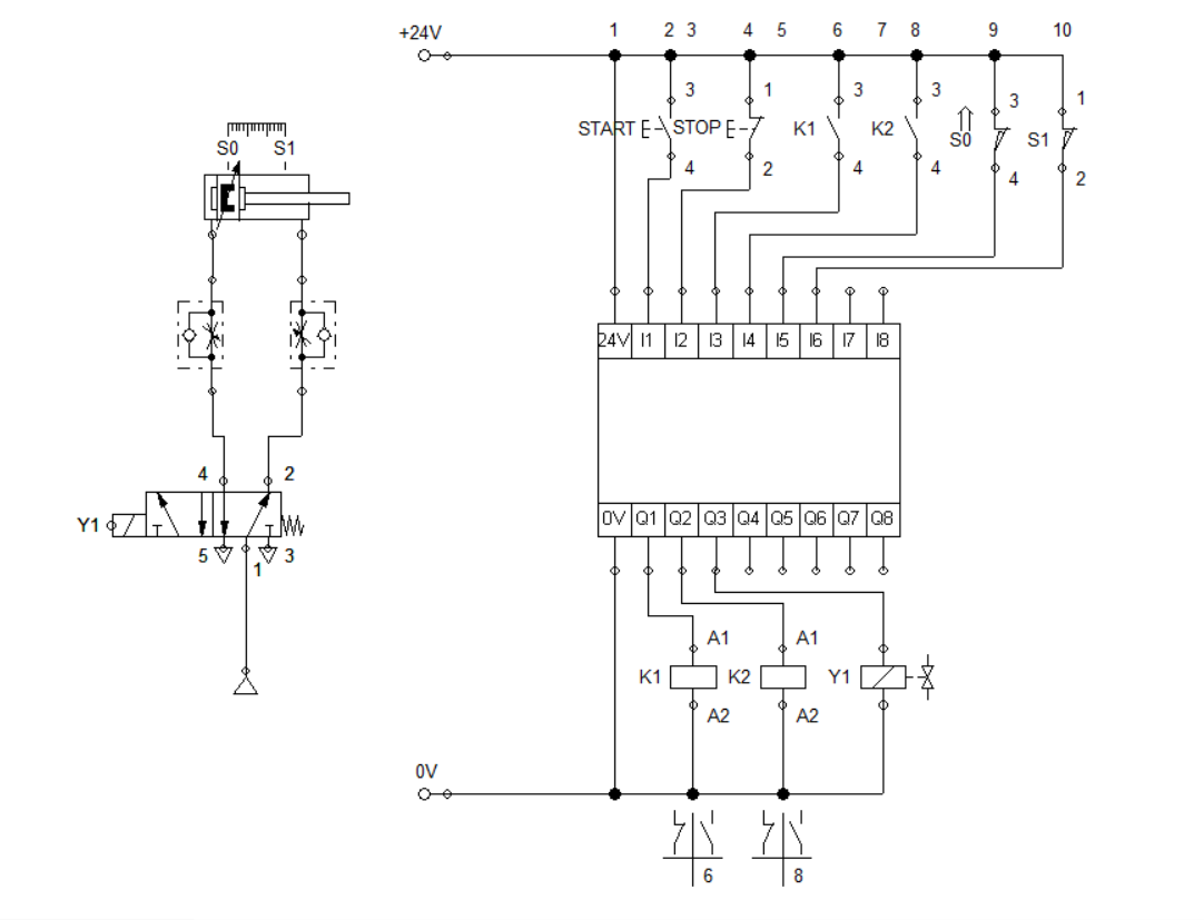
Figure 1: Automatic Washing System using the Logic Module
We start by building the pneumatic circuit that retracts and extends the cylinder. Similar to the previous blog, the circuit consist of a double acting cylinder, a one-way flow control valve and a single solenoid 5/2 way directional valve. The circuit is configured as shown in Figure 1. After the pneumatic circuit is connected, we set the input and output of the logic module. The input ports are connected to a pair of push button, a pair of relay contact and a pair of sensor (limit switches) while the output is connected to a pair of relay and a solenoid.
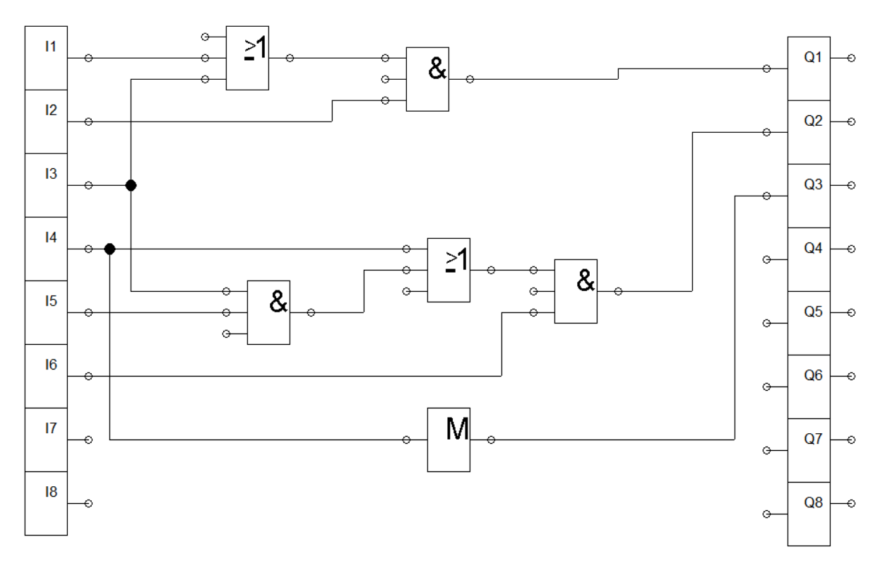
Figure 2: Logic controller
As stated in the scenario in section 1, the washing process start and stop by pressing a button. We connect the start and stop button in I1 and I2 and connect it to an AND logic. The combination is then connected to an OR gate with K1 contact to sustain activation of the K1 relay. The output of the combination is feed to relay coil K1. We take note that stop button is normally closed which makes relay K1 activates when the push button is pressed. The logic simulation is shown in Figure 3.
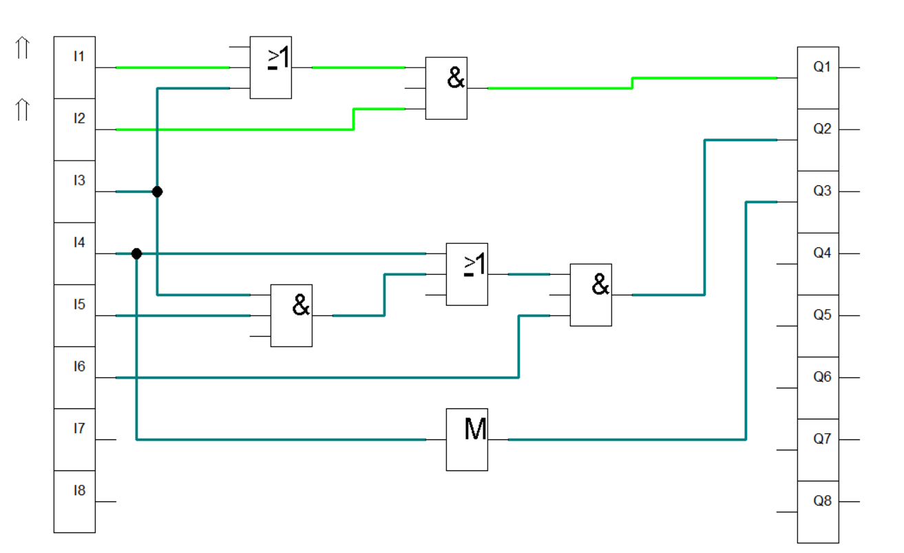
Figure 3: Activating K1
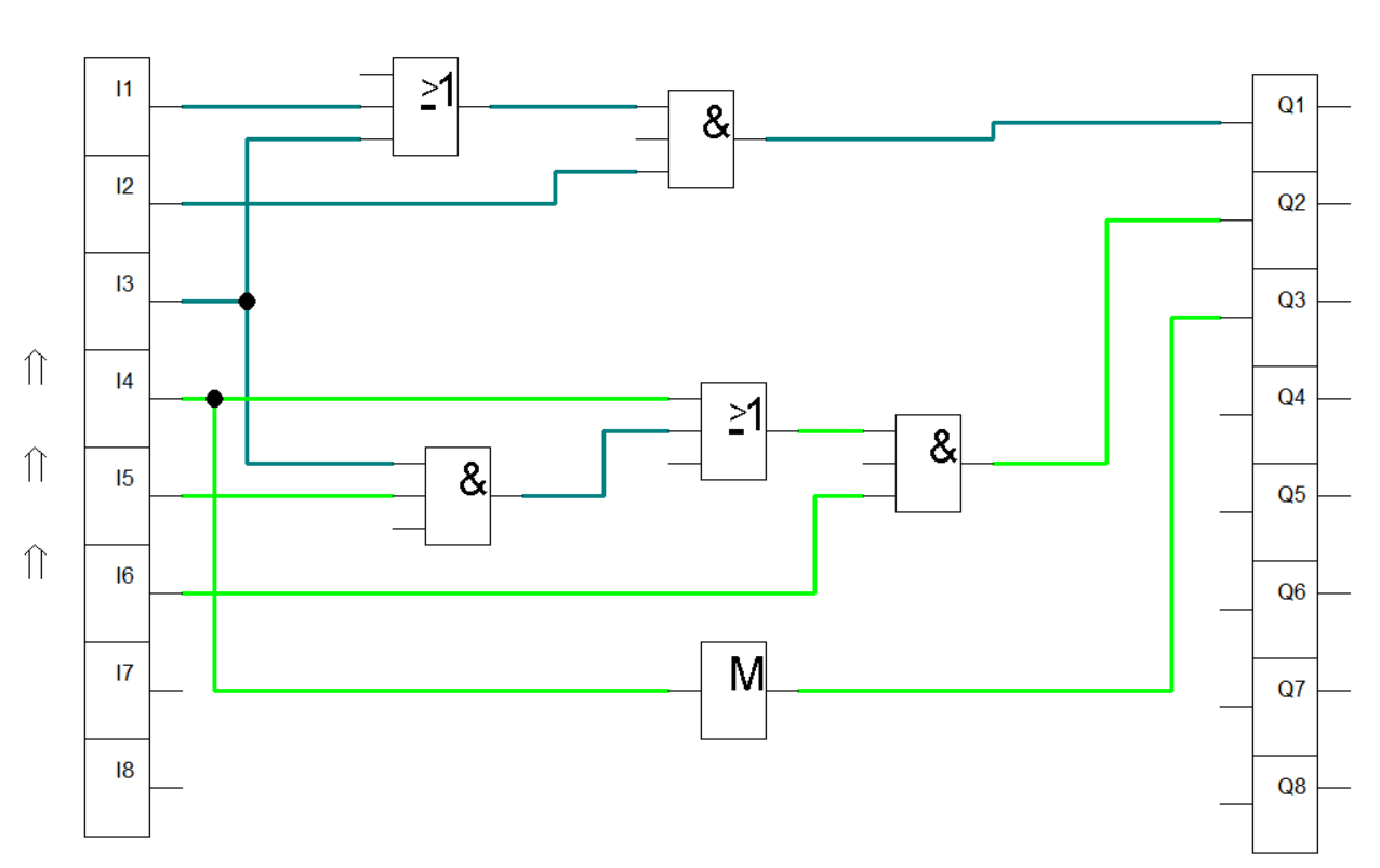
Figure 4: Activating K2 and Y1
We set up I3 and I4 for the relay contact. We connect to an AND gate the S0 and K1 and to an OR gate with K2. The combination is then feed to an AND gate together with S1 to establish the activation of relay K2. This enable the system to continuously run the washing process until stop button is activated. The logic simulation is shown in Figure 4. For the solenoid Y1, contact K2 is feed to a buffer to enable activation. When Y1 is activated, 5/2 way DCV actuates the cylinder to extend. The The full simulation is shown in Figure 5.
3. Conclusion
We created an automation circuit using a programmable logic controller, shown in Figure 1. Automating processes required a correct logic controllers that interprets the set of inputs ( relays contact, sensors). In this blog, we create a circuit for an automatic washing system using the logic module (controller) which displays the configuration to be done to achieve the described process.
4. References
[1] Pneumatic Basic Level. online access
[2] Pneumatic Advanced Level. online access
[3] Electro-pneumatic Basic Level. online access
[4] Electro-pneumatic Advance Level. online access
[5] Programmable Logic Controller Basic Level. online access
(Note: All images and diagram in the text are drawn by the author (@juecoree) except those with separate citation.)
If your are Interested in pneumatic and electro-pneumatic system, you can read:
1. Pneumatic Basics: Direct Control
2. Pneumatic Basics: Indirect Control
3. Pneumatic Basics: AND and OR Logic
4. Pneumatic Basics: Memory Circuit and Speed Control
5. Pneumatic Basics: Dependent control
6. Pneumatic Basics: Multiple Actuators
7. Electro-pneumatic Basic: AND and OR Logic
8. Electro-pneumatic Basics: Interlocking, Latching and XOR logic
9. Electro-pneumatic Basics: Distribution of Workpiece
10. Electro-pneumatic Basic: Ejecting a workpiece
11. Electro-pneumatic Basics: Basic Automation
12. Electro-pneumatic Basics: Automation with Counter
12. Electro-pneumatic Basics: Automating with Timer
13. Electro-pneumatic Basics: Cementing Press (Time Dependent Control)
14. Electro-pneumatic Basics: Embossing Device
15. Electro-pneumatic Basics: Bending Device
16. Electro-pneumatic Basics: Introduction to Logic Module
Posted with STEMGeeks
Congratulations @juecoree! You have completed the following achievement on the Hive blockchain and have been rewarded with new badge(s) :
You can view your badges on your board and compare yourself to others in the Ranking
If you no longer want to receive notifications, reply to this comment with the word
STOPTo support your work, I also upvoted your post!