Hydraulic Basics: Direct Control
1. Introduction
In this blog, we introduce a hydraulic system and create the basic controls for hydraulic cylinders. The difference between the pneumatic and hydraulic system is the fluid being used to control the motions of the valves and cylinders. Pneumatic system used compressible gas while hydraulic system used seemingly incomprehensible fluid such as water or mineral oil. Both system are equally important in any application. In the next section, we present the basic circuit to actuate a hydraulic cylinder in details.
The circuit that to be simulated in this blog provides a solution to a given problem or scenario. For direct control, the problem is described as
A single acting or a double acting hydraulic cylinder clamps a component when a pushbutton is pressed. As long as the push button is activated the cylinder is to remain in the clamped position. If the push button is released, the clamp is to retract. The retracting and extending motion is feed with with 50% of the input fluid (water or oil) pressure.
2. Circuit and Simulation
The simplest level of control for the single or double-acting hydraulic cylinder is by means of direct control. The cylinder is directly actuated via a manually or mechanically actuated valve. In this blog, the hydraulic circuit consist of a double-acting cylinder, a 5/2 way directional control valve with spring return, a pair of one-way flow control valve, and a pair of tank. The circuit is shown in Figure 1.
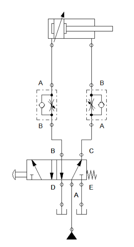
Figure 1: Hydraulic Circuit for Direct Control
When we pressed the push button, the 5/2 way DCV open up port B. This enables fluid to flow through the hydraulic cylinder. We need to press the button continuously for the cylinder to reach full extended position. Releasing the push button before it fully extends, retracts the cylinder tot initial position. If you want to not be burden with pressing the push button, you can change the button to a detent switch. The the fluid flow across the cylinder at any given instance is shown in Figure 2 and Figure 1.
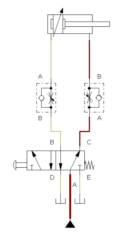
Figure 2: Initial state
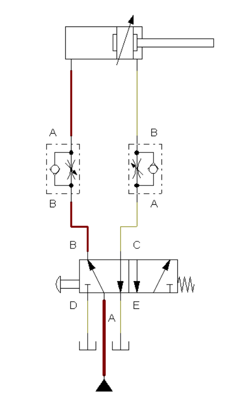
Figure 2: Actuated State
For the circuit to perform correctly, the port D and E should be connected to a tank instead of a shut off point. The tank enables the fluid to be drain during the activation of the system. At initial condition, the cylinder is feed with fluid pressure from port C to remain retracted. Once push button is pressed, the directional valve shifted the opening from port C to port B. The fluid pressure at port B caused the cylinder to extend. In case the button is released, the valve and cylinder return to initial state. The animated simulation is shown in Figure 4.
Figure 4: Full Simulation for Direct Control
3. Conclusion
The directional control valve is actuated by pressing the push button that result to the cylinder extending. Similar to pneumatic 5/2 DCV, the hydraulic 5/2 way shifted the valve opening for the control action to happen. A notable difference between pneumatic and hydraulic in terms of the circuit is the use of tank of the hydraulic valves where pneumatic valve just put opening at its exhaust.
4. References
[1] Hydraulic Basic Level. online access
[2] Hydraulic Advance Level. online access
(Note: All images and diagram in the text are drawn by the author (@juecoree) except those with separate citation.)
If your are Interested in pneumatic and electro-pneumatic system, you can read:
1. Pneumatic Basics: Direct Control
2. Pneumatic Basics: Indirect Control
3. Pneumatic Basics: AND and OR Logic
4. Pneumatic Basics: Memory Circuit and Speed Control
5. Pneumatic Basics: Dependent control
6. Pneumatic Basics: Multiple Actuators
7. Electro-pneumatic Basic: AND and OR Logic
8. Electro-pneumatic Basics: Interlocking, Latching and XOR logic
9. Electro-pneumatic Basics: Distribution of Workpiece
10. Electro-pneumatic Basic: Ejecting a workpiece
11. Electro-pneumatic Basics: Basic Automation
12. Electro-pneumatic Basics: Automation with Counter
12. Electro-pneumatic Basics: Automating with Timer
13. Electro-pneumatic Basics: Cementing Press (Time Dependent Control)
14. Electro-pneumatic Basics: Embossing Device
15. Electro-pneumatic Basics: Bending Device
16. Electro-pneumatic Basics: Introduction to Logic Module
17. Electro-pneumatic Basics: Automating with Logic Controller
18. Electro-pneumatic Basics: Logic Controller for Multiple Actuators
19.Electro-pneumatic Basics: Time-dependent control with Logic Controller.
Posted with STEMGeeks