Hydraulic Basics: Dual Pressure Value and the AND Logic
1. Introduction
In pneumatic and hydraulic system, shuttle valve and dual pressure valve enables logic function to be simulated in a circuit. Dual pressure valve gives an output when both input port are activated. Dual pressure valve represents the logic AND function. In this blog, we explore and create a hydraulic circuit that AND logic.
The circuit to be simulated is based from the problem or scenario. For AND logic, the problem is described as
A double acting hydraulic cylinder is to extends only if a work piece is inserted in the retainer, a guard has been lowered and the operator presses the push button valve. Upon release of the push button or if the guard is no longer in its lower position, the cylinder is to retract to initial position. The motion should be limited to 50%.
The problem requires two push button for the cylinder to extend. This push button represents the guard and operator action. A flow control valve enables he cylinder extends and retracts with 50% speed. In the next section the hydraulic circuit and simulation is shown in details.
2. Circuit and Simulation

In Figure 1, we used three 3/2 way valve with varied actuation mechanism, a hydraulically actuated 5/2 way directional valve, a dual pressure valve, a double-acting cylinder and one sensor for AND logic. The pair 3/2 way directional valve with push button serves as the input to the dual pressure valve while the 3/2 way directional control valve with roller detects the fully extended cylinder. The 5/2 way directional valve have two hydraulically actuated ports. This ports controls the shifting of output opening in the 5/2 way DCV.
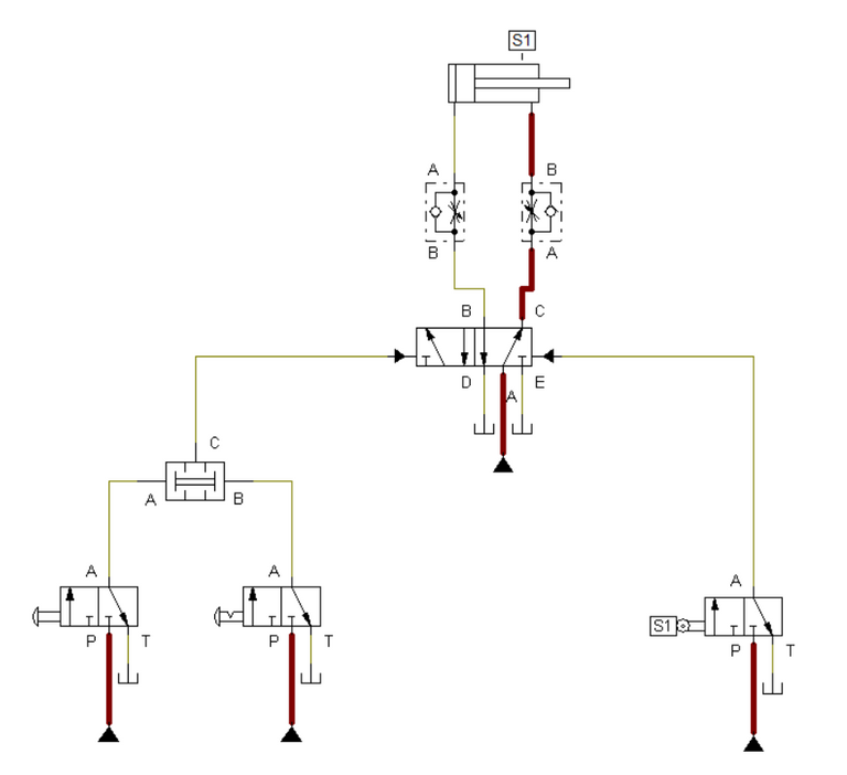
 Figure 2: The circuit at initial state.
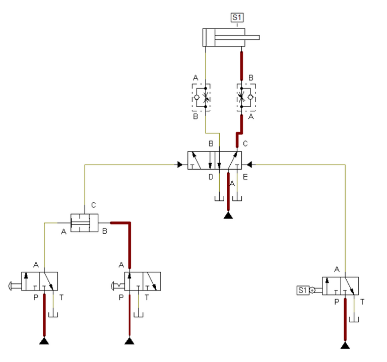
 Figure 3: One input button is pressed.
At initial state, the hydraulic cylinder is retracted hence the port C of the 5/2 way DCV applied fluid pressure to it. When a single input button is pressed, the dual pressure valve is half open and no fluid pressure at its output port, as shown in Figure 3. Without any fluid pressure applied to hydraulically actuated port of 5/2 way DCV, the output does not switched to port B. This caused the cylinder to remain retracted.

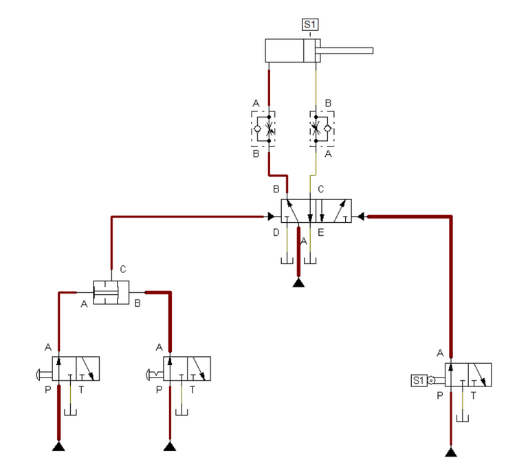
Figure 4: Two input button is activated.
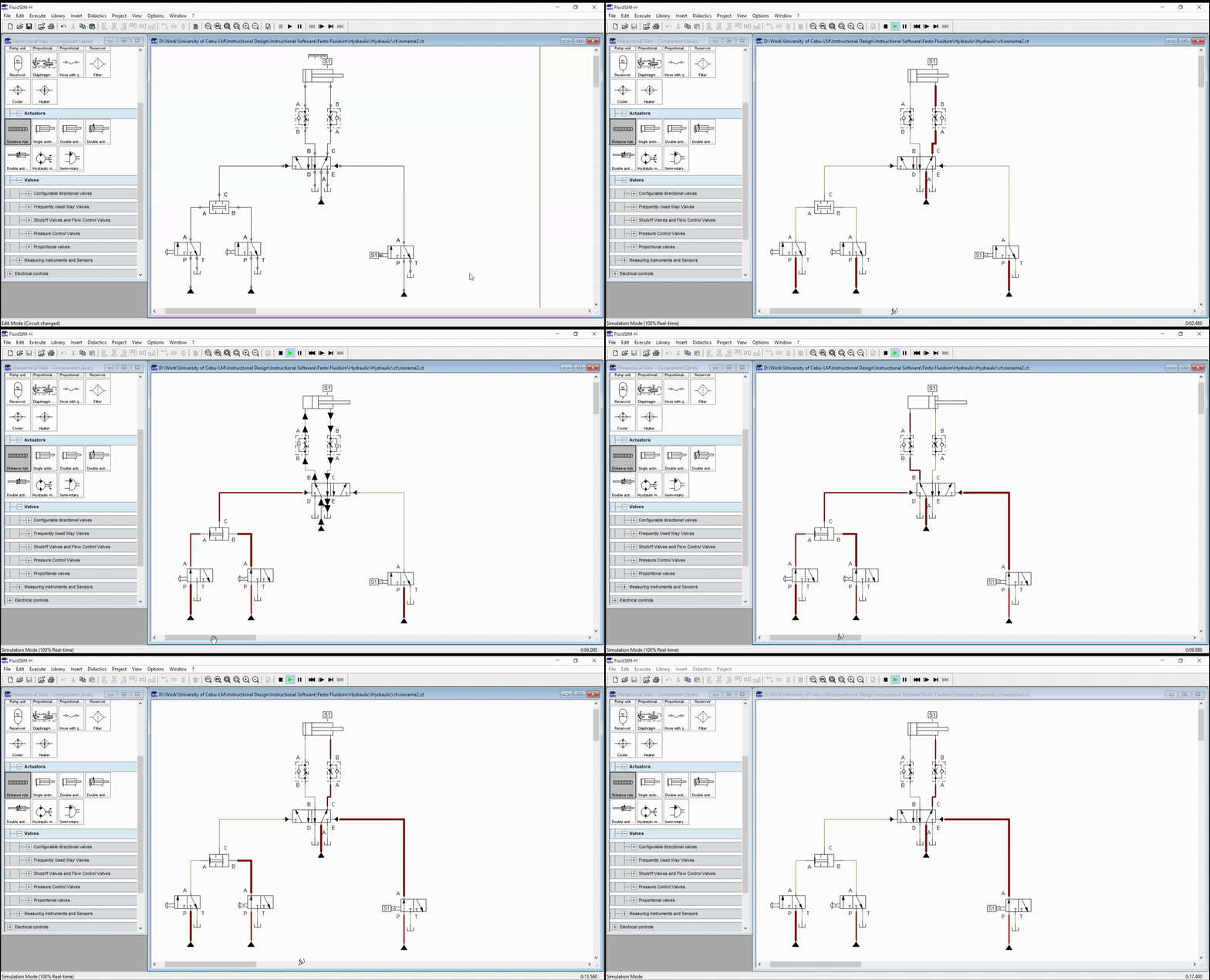
Once two input button is pressed, the dual pressure valve is activated and allows fluid pressure to activate the 5/2 way DCV. This yield to switching from port C to B in the 5/2 way DCV. After port B opens, the fluid pressure actuates the cylinder to extend. Once fully extended, the sensor (limit switch) S1 detects and confirm the full extension. When either input button is released, the 3.2 way DCV with roller activates the switching back to port C in 5/2 way DCV and retract the cylinder. The animated simulation is shown in Figure 5.

Figure 5: Full Simulation
3. Conclusion
A dual pressure valve gives us a convenient way to simulate the AND logic in hydraulic circuit. The dual pressure valve needs a pair of input to activate which is suited for AND logic simulation. Also, dual pressure valves offers an interlock mechanism that enables a pair of condition is to be achieved prior activating.
4. References
[1] Hydraulic Basic Level. online access
[2] Hydraulic Advance Level. online access
(Note: All images and diagram in the text are drawn by the author (@juecoree) except those with separate citation.)
Hello Hive! If your are interested in pneumatic and hydraulic series, you can read:
Pneumatic and Electro-pneumatic
1. Pneumatic Basics: Direct Control
2. Pneumatic Basics: Indirect Control
3. Pneumatic Basics: AND and OR Logic
4. Pneumatic Basics: Memory Circuit and Speed Control
5. Pneumatic Basics: Dependent control
6. Pneumatic Basics: Multiple Actuators
7. Electro-pneumatic Basic: AND and OR Logic
8. Electro-pneumatic Basics: Interlocking, Latching and XOR logic
9. Electro-pneumatic Basics: Distribution of Workpiece
10. Electro-pneumatic Basic: Ejecting a workpiece
11. Electro-pneumatic Basics: Basic Automation
12. Electro-pneumatic Basics: Automation with Counter
12. Electro-pneumatic Basics: Automating with Timer
13. Electro-pneumatic Basics: Cementing Press (Time Dependent Control)
14. Electro-pneumatic Basics: Embossing Device
15. Electro-pneumatic Basics: Bending Device
16. Electro-pneumatic Basics: Introduction to Logic Module
17. Electro-pneumatic Basics: Automating with Logic Controller
18. Electro-pneumatic Basics: Logic Controller for Multiple Actuators
19.Electro-pneumatic Basics: Time-dependent control with Logic Controller.
Hydraulics
20. Hydraulic Basics: Direct Control
21. Hydraulic Basics: Indirect Control
Posted with STEMGeeks