Electro-Hydraulic Basics: Direct and Indirect Control (Part 2 of 2)
In the previous blog, we discussed direct and indirect control by focusing on circuit that used single solenoid valve. In this blog, we elaborate on direct and indirect control by focusing of double solenoid valves and integrating memory circuit. Similar to the previous blogs, we used a problem or scenario that enables us to present a circuit for direct and indirect control with double solenoid valves. The same problem (describe in the previous blog) is used. The problem is described as
A double-acting hydraulic cylinder extends when an electrical push button is pressed. Upon release of the push button the cylinder is to retract. The double-acting cylinder must must be retracted or extended with 50% of the input air pressure.
Similar to the previous blog, we solve the problem using two method, direct and indirect control, but we implement the method using a double solenoid 5/2 way directional valve as main control valve. Also, we integrate a memory circuit so that the cylinder fully extends even though the push button is released. In the next section, we present the circuit and discussed in details.
2. Circuit and Simulation
The hydraulic circuit for both method consist of a double acting cylinder, a pair of one-way flow control, and a double solenoid actuated 5/2 way directional control valve. The double solenoid 5/2 way directional control valve allows us to control the extending and retracting of the solenoid. The main difference with the single solenoid valve implementation is that the retracting actuation is automatically induced by a spring. The circuit configuration is shown in Figure 1.
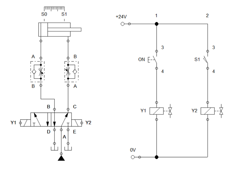
Figure 1: Electro-Hydraulic Circuit for Direct Control
Also, the circuit address one flaw in the previous blog's implementation. In the previous blog, the circuit automatically return to initial state or retracted position when we quickly release the button without fully extending it. This flaw is corrected by integrating a simple memory circuit. The memory circuit can only be wired if we used a double solenoid rather than a single solenoid valve. To configure the memory circuit, we need sensors to detect the position of the cylinder at any instance. For the circuit in Figure 1, we employ two sensor which is placed at the full retracted and extended position. Sensor S0 is at the initial state while sensor S1 is at fully extended state.
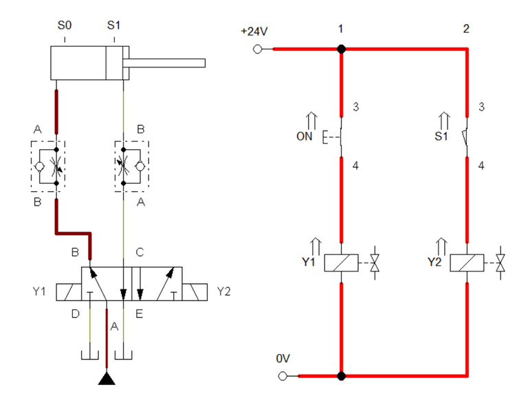
Figure 2: Push button is activated.
For direct control using double solenoid valve, the cylinder extends once the push button is pressed to actuate the solenoid Y1. When Y1 is energized, the 5/2 way DCV switched the output port from C to B. This caused the cylinder to extend and hit sensor S1. Sensor S1 send a signal to activated solenoid Y2. This result to activating Y2 which eventually returns the cylinder to initial state. The fluid and electrical flow is shown in Figure 2 while Figure 3 shows the animated simulation.
Figure 3: Full Simulation
For indirect control, we employed two relays to drive each solenoid. Similar to direct control, the solenoid Y2 is actuated by the sensor S1 so that the cylinder continues to extends even an early released of the push button. Electricity energized relay K1 when the push button is pressed. This causes the latching contact K1 to close. Once cylinder is fully extended, sensor S1 activates and energized K2. Activating K2 results to activating the solenoid Y2. The circuit configuration is shown in Figure 4. The simulation is shown in Figure 5.
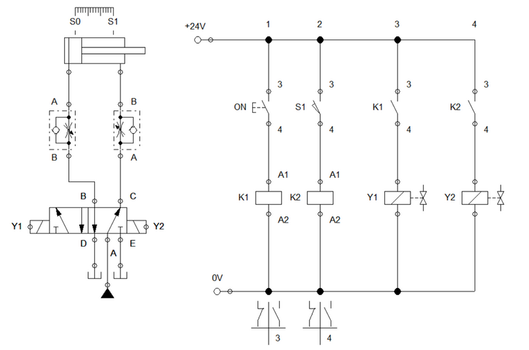
Figure 4: Electro-Hydraulic Circuit for Indirect Control
Figure5: Full Simulation
3. Conclusion
In this blog, we discussed a different implementation of direct and indirect control using the double solenoid control valve. In this blog, we manually actuate the cylinder to retract rather using a spring return. This enables us to integrate memory circuit so that the cylinder can fully extend after early releasing of the push button. This configuration is practically used as the basis for automating simple process.
4. References
[1] Hydraulic Basic Level. online access
[2] Hydraulic Advance Level. online access
[3] Electro-Hydraulic Basic Level. online access
[4] Electro-Hydraulic Advance Level. online access
(Note: All images and diagram in the text are drawn by the author (@juecoree) except those with separate citation.)
If your are interested in pneumatic and hydraulic series, you can read:
Pneumatic and Electro-pneumatic
1. Pneumatic Basics: Direct Control
2. Pneumatic Basics: Indirect Control
3. Pneumatic Basics: AND and OR Logic
4. Pneumatic Basics: Memory Circuit and Speed Control
5. Pneumatic Basics: Dependent control
6. Pneumatic Basics: Multiple Actuators
7. Electro-pneumatic Basic: AND and OR Logic
8. Electro-pneumatic Basics: Interlocking, Latching and XOR logic
9. Electro-pneumatic Basics: Distribution of Workpiece
10. Electro-pneumatic Basic: Ejecting a workpiece
11. Electro-pneumatic Basics: Basic Automation
12. Electro-pneumatic Basics: Automation with Counter
12. Electro-pneumatic Basics: Automating with Timer
13. Electro-pneumatic Basics: Cementing Press (Time Dependent Control)
14. Electro-pneumatic Basics: Embossing Device
15. Electro-pneumatic Basics: Bending Device
16. Electro-pneumatic Basics: Introduction to Logic Module
17. Electro-pneumatic Basics: Automating with Logic Controller
18. Electro-pneumatic Basics: Logic Controller for Multiple Actuators
19.Electro-pneumatic Basics: Time-dependent control with Logic Controller.
Hydraulics and Electro-Hydraulic
20. Hydraulic Basics: Direct Control
21. Hydraulic Basics: Indirect Control
22. Hydraulic Basics: Dual Pressure Value and the AND Logic
23. Hydraulic Basics: Shuttle Valve and the OR Logic
24. Hydraulic Basics: Sequencing Multiple Cylinders (Actuators)
25. Hydraulic Basics: Automating Multiple Cylinders (Actuators)
26. Electro-Hydraulic Basics: Direct and Indirect Control (Part 1 of 2)
Posted with STEMGeeks