Hydraulic Basics: Shuttle Valve and the OR Logic
1. Introduction
In pneumatic and hydraulic system, shuttle valve enables OR logic function to be simulated in a circuit. A shuttle valve has a pair of input ports and an output. The shuttle valve opens the output port by either of the input port is actuated. In this blog, we used a problem to demonstrate the use of a shuttle valve in hydraulic system and showcase how to implement OR logic. The problem is describe as
A double-acting hydraulic cylinder transfers components from a point A to a point B. Either a push button or a foot pedal actuates the cylinder to extend. A 3/2 way roller lever valve is to be used to detect the full extension of the cylinder. The cylinder extends and retracts about 50% of input fluid pressure.
The problem specify three conditions. First, the cylinder can be operated by either a push button or a foot pedal. Next, The cylinder automatically retracts after sensor (limit switch) of 3/2 way directional control valve detects the cylinder's piston head. Lastly, The speed of motion is controlled at 50%. In the next section, we create and discussed the hydraulic circuit in details as to the required conditions.
2. Circuit and Simulations
As mentioned earlier, a shuttle valve simulates the OR logical function in hydraulic system. The circuit consists of three 3/2 way directional valve with different actuating mechanism (push button, foot pedal, and limit switch). The push button and the foot pedal is connected directly to the input of the shuttle valve. This mechanical actuating devices controls the extending of the cylinder. The output of the shuttle valve is connected to one of the hydraulically actuated port of the 5/2 way DCV while the other port is for the sensor activated 3/2 way DCV. The circuit is shown in Figure 1.
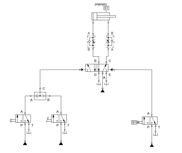
Figure 1: Hydraulic circuit for OR Logic
At initial condition, the 5/2 way DCV allows fluid pressure to flow across the retracting port of the double-acting cylinder. This enables the cylinder to remain retracted unless the port C of the 5/2 way DCV is closed. When we press either the push button or the foot pedal, the shuttle valve is activated and fluid flows across the actuating port of the 5/2 way DCV. When the 5/2 way DCV is actuated, the output port shifted from port C to port B. This yield to the cylinder extending as the fluid pressure flows across it. This is shown in Figure 2 and Figure 3 for push button and foot pedal respectively.
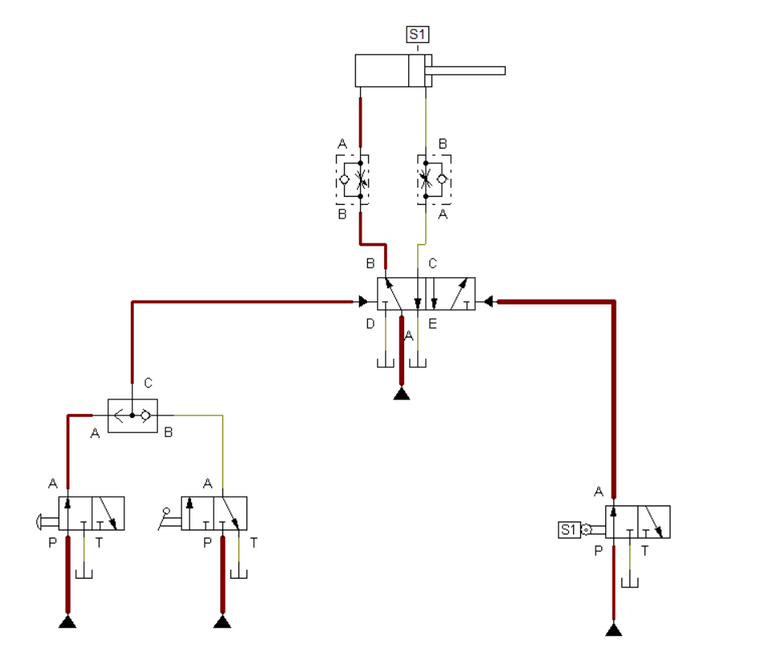
Figure 2: Push button is pressed.
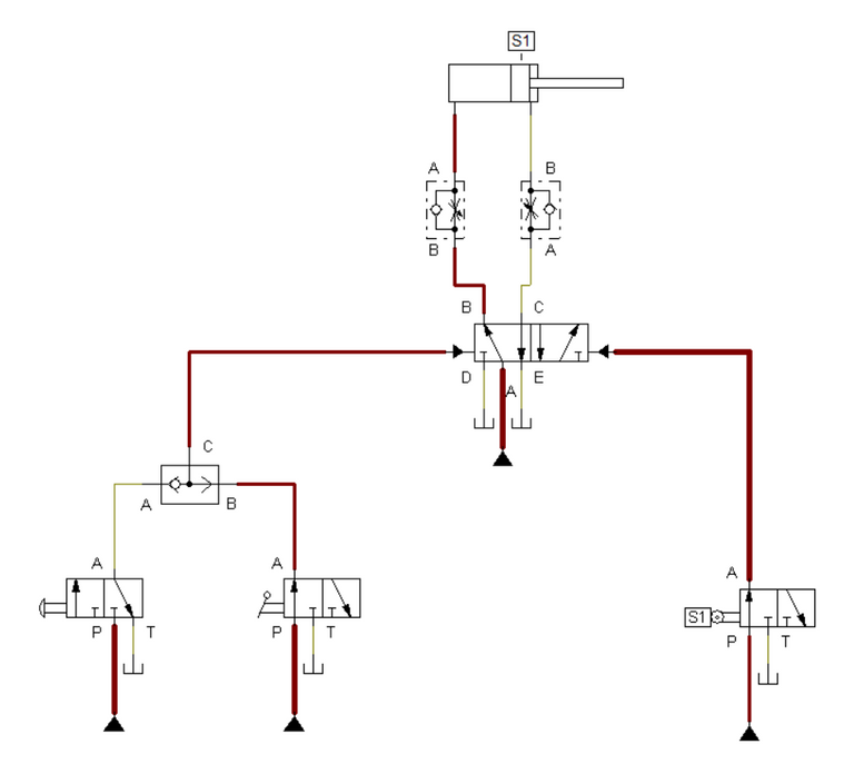
Figure 3: Foot pedal is pressed.
Once the cylinder fully extend, sensor S1 detects it and transmit a signal to activate the 3/2 way DCV. The activation of 3/2 way DCV with limit switch caused the 5/2 way DCV to return to initial state. The 5/2 way closes the port B and opens the port C for the cylinder to retract and return to initial state. The simulation is shown in Figure 4.
Figure 4: Full Simulation
3. Conclusion
A shuttle valve enables an OR logical function to be integrated in a pure hydraulic system. The cylinder extends with either actuation mechanism is activated at any given time. The OR logic is applied in hydraulic system for scenarios that can be operated locally or remotely.
4. References
[1] Hydraulic Basic Level. online access
[2] Hydraulic Advance Level. online access
(Note: All images and diagram in the text are drawn by the author (@juecoree) except those with separate citation.)
Hello Hive! If your are interested in pneumatic and hydraulic series, you can read:
Pneumatic and Electro-pneumatic
1. Pneumatic Basics: Direct Control
2. Pneumatic Basics: Indirect Control
3. Pneumatic Basics: AND and OR Logic
4. Pneumatic Basics: Memory Circuit and Speed Control
5. Pneumatic Basics: Dependent control
6. Pneumatic Basics: Multiple Actuators
7. Electro-pneumatic Basic: AND and OR Logic
8. Electro-pneumatic Basics: Interlocking, Latching and XOR logic
9. Electro-pneumatic Basics: Distribution of Workpiece
10. Electro-pneumatic Basic: Ejecting a workpiece
11. Electro-pneumatic Basics: Basic Automation
12. Electro-pneumatic Basics: Automation with Counter
12. Electro-pneumatic Basics: Automating with Timer
13. Electro-pneumatic Basics: Cementing Press (Time Dependent Control)
14. Electro-pneumatic Basics: Embossing Device
15. Electro-pneumatic Basics: Bending Device
16. Electro-pneumatic Basics: Introduction to Logic Module
17. Electro-pneumatic Basics: Automating with Logic Controller
18. Electro-pneumatic Basics: Logic Controller for Multiple Actuators
19.Electro-pneumatic Basics: Time-dependent control with Logic Controller.
Hydraulics
20. Hydraulic Basics: Direct Control
21. Hydraulic Basics: Indirect Control
22. Hydraulic Basics: Dual Pressure Value and the AND Logic
Posted with STEMGeeks