Electro-pneumatic Basics: Automating with Timer
1. Introduction
In the previous blogs, we explain on how to automate a process with a specific number of repetition. In this blog, we create a circuit that automates a process that is time-dependent.
A container of washers is to be dipped in and out of the cleaning bath. The START and STOP for the continuous movement is to be achieved by actuating pushbutton each. On actuating the STOP pushbutton the container should stop at the top (retracted position). By switching off the main valve the container should not fall into the bath with an impact. A delay of 10 seconds from the extended to retracted position is observed.
The problem specified that a delay of 10 seconds is observed before extending or retracting the double-acting cylinder. The circuit and the simulation is presented with details in next sections.
2. Circuit and Simulation

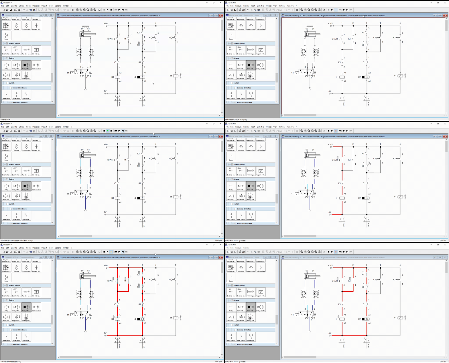
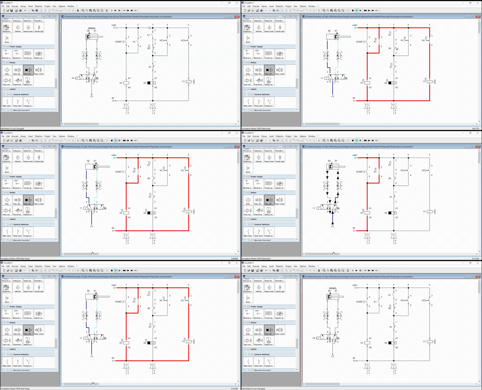
Figure 1: Electro-pneumatic circuit with Timer (without STOP button)
A double acting cylinder simulates the dipping of the washer in the cleaning bath while the flow control valve ensures the extending and retraction is maintained at a 50% speed. The double-acting cylinder is actuated by a single solenoid 5/2-way directional control valve with spring return. On the other hand, the ladder diagram performs the control mechanism to achieve what was asked in the problem or scenario. It is composed of a push button, a relay and a timer relay. The timer relay in Figure 2 established the time interval between retracting and extending of the cylinder. The relays are latched so that the dipping process is continuous.

Figure 2: Start button is pressed.
In Figure 2, the push button is pressed which result to a current flow across the relay coil K1. When K1 is energized, all K1 contacts shifted from normally open to closed position or in reverse. For the circuit in Figure 1, K1 closes and activates the relay timer K2. The timer K2 is a off-delay contacts that means it cut off the current after a specific time interval.

Figure 3: Timer relay K2 is activated.
After the K2 relay is energized, all the K2contacts shifted to closed state. This allowed current to flow through the solenoid valve Y1. Once Y1 is activated, the 5/2-way directional valve opened port 4 to actuates the double-acting cylinder. When the piston has fully extended and reach the S1 position, the sensor S1 cut off the current flow to K2 relay. If the K2 relay is not energized, all the make switches will go back to their initial position. The relay timer holds the activation state of the solenoid after the set time interval. The timer is set to 10 seconds before retraction occurs. The full simulation is shown in Figure 4.

Figure 4: Simulation for dipping process.
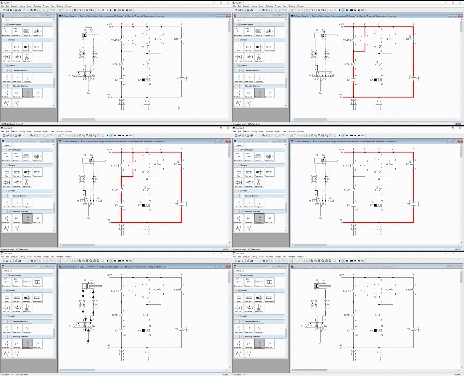
The mechanism presented in Figure 4 achieved the dipping process as defined in the problem. However, the process do not stop unless we cut the electrical or the air supply. To manually stop the process, we need to update the circuit by adding stop button before the relay K1. The updated circuit is shown in Figure 5 while Figure 6 shows the simulation.

Figure 5: Electro-pneumatic circuit for Automatic Washing System with Timer .

Figure 6: Full Simulation .
3. Conclusion
We created a basic automation circuit with counter, shown in Figure 5. Delaying a process step is done by integrating a timer to the basic automation circuit in electro-pneumatic. The timer stops the activation of the solenoid once the set time is achieved. In this blog, we create a circuit for an automatic washing system with timer that shows how to configure a basic automated process with a delayed reaction or step in between the process in electro-pneumatic.
4. References
[1] Pneumatic Basic Level. online access
[2] Pneumatic Advanced Level. online access
[3] Electro-pneumatic Basic Level. online access
(Note: All images and diagram in the text are drawn by the author (@juecoree) except those with separate citation.)
If your are Interested in pneumatic and electro-pneumatic system, you can read:
1. Pneumatic Basics: Direct Control
2. Pneumatic Basics: Indirect Control
3. Pneumatic Basics: AND and OR Logic
4. Pneumatic Basics: Memory Circuit and Speed Control
5. Pneumatic Basics: Dependent control
6. Pneumatic Basics: Multiple Actuators
7. Electro-pneumatic Basic: AND and OR Logic
8. Electro-pneumatic Basics: Interlocking, Latching and XOR logic
9. Electro-pneumatic Basics: Distribution of Workpiece
10. Electro-pneumatic Basic: Ejecting a workpiece
11. Electro-pneumatic Basics: Basic Automation
12. Electro-pneumatic Basics: Automation with Counter
Posted with STEMGeeks
Goodness. You have an entire series for people to browse through here.
!discovery 41
Appreciate the support. I am glad to share STEM and engineering content to the community.
This post was shared and voted inside the discord by the curators team of discovery-it
Join our community! hive-193212
Discovery-it is also a Witness, vote for us here
Delegate to us for passive income. Check our 80% fee-back Program