ELECTROMAGNETIC RADIATION: Huygens’ Principle And The Principle Of Superposition.
Huygens explained how water waves travelled by saying something quite original: every point on the front of a wave gave rise to another wave centred on that point. At first sight this looked as if the wave would descend into chaos, and Huygens’ model skated over this possibility. He used his idea to explain two main effects: how light travels in a straight line, and why light spreads out after passing through a small aperture (diffraction). But to explain both effects properly another principle is needed: the principle of superposition.

When two water wave pulses meet, they pass through each other. However, at the meeting point the wave amplitudes add: two crests produce a larger crest, and, similarly, two troughs make a deeper trough. A crest meeting an equal-sized trough produces an instant of completely flat water. So, the principle of superposition is a situation by which the amplitudes of two waves that occupy the same space at the same time simply add together. This effect is called interference. Phase is short for phase angle. When a wave travels one wavelength the phase angle changes by 2π radians or 360°. Phase difference, Δ(phase), between two superposing waves depends on wavelength and the difference in path distance, Δ(path), travelled by the two waves coming from the same source via different paths. When the path difference is a whole wavelength there is no phase difference. For half a wavelength, the phase difference places crest over trough.
The phase relationship is:
Δ(phase) = 2π/λ × Δ(path)
Huygens’ wave model of light explains how waves propagate as follows. Imagine that each point on a straight wavefront (equivalent to the water wave crest) is the source of another wave (i.e. as the wavefront ‘collapses’). Then the waves (or wavelets) from each of these point sources interfere with the wavelets from the other points in such a way that the only places where they add together are in the forward direction. Thus a plane (straight-fronted) wave would move forward as a plane wave and therefore light would travel in straight lines.
But note that at the edges of the plane wavefront, the wavelets would have no supporting wavelets to interfere with. The waves here could propagate sideways, in other words, diffraction would occur.
INTERFERENCE AND WAVELENGTH
YOUNG’S TWO-SLIT INTERFERENCE EXPERIMENT
This experiment is the best known of those designed by Thomas Young in 1801 in support of the wave theory of light.
Two slits are illuminated by a plane wave. Ebohr1.svg: en:User:Lacatosias, CC BY-SA 3.0
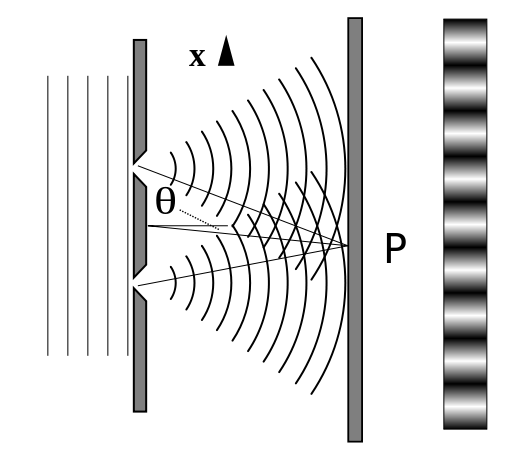
The figure shows a parallel beam of light (e.g. from a distant point object) reaching an opaque screen with two narrow slits in it. Light is diffracted at each slit and the spreading beams overlap. This means that, at any point along a line such as XY, light is received from both slits A and B. The contributions from the slits reaching a point such as P may be in phase or out of phase, and the resulting intensity at P could be anything from zero to double the contribution from any one slit.
What exactly happens at P depends on the geometry, in fact, on the difference in the path lengths AP and BP.
- If AP – BP is zero, a whole wavelength or a whole number of wavelengths, the contributions are in phase, and we have a brightness at P.
- If AP – BP is a half wavelength or an odd number of half wavelengths, the contributions are exactly out of phase, destructive interference occurs and there is a darkness at P.
You can imagine that as the point P in the figure moves along XY, the path difference changes and P will be alternately in bright and dark zones, called interference fringes. These fringes are easy to see when you look at a distant lamp (say, 3 metres away) through two slits scratched about a millimetre apart in a blackened microscope slide. This is Young’s two-slit interference experiment. This experiment can be used to measure the wavelength of light.
MEASURING THE WAVELENGTH OF LIGHT
The figure below shows a diagram with angles drawn to a more realistic scale. The slit separation s is a millimetre or two, and the distance D from the slits to the plane of observation (XY) is several metres. O is a point equidistant from the slits A and B. So the path difference is zero and O is in the centre of a bright fringe. P is distance x from O, chosen so that P is in the centre of the next bright fringe.
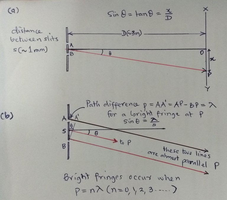
An illustration of Young's experiment drawn by me, showing the difference in path length for light through two slits causing phase differences and creating fringes.
Look at the triangle in the figure. The angle θ is very small, so that sin θ = tan θ, and we can write:
sin θ = tan θ = x/d
The second figure shows the detail nearer the two slits. The path difference between light reaching P from A and B is p (AA’). As the waves add up to brightness this path difference must be one wavelength. The two lines AP and BP are almost parallel, since P is so far away. Thus the angle ABA’ is aiso θ, and we can write:
sin θ = path difference/slit separation
sin θ = λ/s
which is usually rearranged as
λ = s sin θ
In general, bright fringes occur at all angles that involve whole wavelength path differences, i.e.
nλ = s sin θ
where n is a whole number.
The spacing between fringes
Look at the above figure again. Suppose that P is the position of the first bright fringe. OP is now Δx, the spacing between two fringes. As before sin θ = Δx/D or Δx = D sin θ
Looking at the angle near the slit. The path difference is now just one wavelength. So we have sin θ = λ/s and putting in this value we can write the fringe separation as
Δx = λD/s
This relationship applies with good accuracy to all the fringes close to the centre of the fringe system.
Taking measurements
The fringes produced by the arrangement shown are viewed through either a microscope eyepiece with a micrometer scale (marked in millimetres) or a movable (travelling) microscope mounted on a vernier scale. The fringe separation is measured by counting a whole number n of fringes as many as possible – and measuring the value of x shown in the figure.
D is measured with a good steel tape. A travelling microscope (or some optical imaging method) may be used to measure the small distance s. These values are then inserted in the equation
λ = xs/Dn
to calculate the wavelength of light, λ.
COHERENCE
We do not observe interference effects if the path difference between two interfering wavelets is longer than about 30 cm, Neither do we see the effects when light is combined from two different sources (two lamps or two stars, say). This is because the waves are emitted randomly, in short bursts, as is illustrated above. Interference still occurs, but the effect is so random and on such a short time scale (about 10-8 s) that it is impossible to observe. For all practical purposes, we can only observe interference when light from the same ‘burst’ is combined: such light is described as coherent (meaning ‘belonging together’). Lasers can emit continuous coherent light – particularly useful for applications of interference effects, such as making holograms.
DIFFRACTION AND IMAGE FORMATION
Diffraction becomes more noticeable when waves pass through a small hole (aperture). A greater fraction of the incident wave energy moves ‘sideways’, and interference effects occur which produce a diffraction pattern of the kind shown in the figure below.
All optical instruments direct light to pass through apertures (or to reflect off mirrors) of finite size. So some diffraction will occur, and the images produced will tend to lack clarity. The image of a small source of light (effectively a point source) is no longer a point, and the diffraction pattern is a more or less inaccurate version of the point object. With larger objects, fine detail is lost as light from separate points on the object reaches the image as overlapping diffraction patterns. Diffraction affects the images made by telescopes, which is one reason why they have to be so large.

I, Dirk Hünniger, CC BY-SA 3.0
DIFFRACTION THROUGH A SLIT
When light goes through a narrow slit it spreads out – just as water waves do. Think of a set of plane waves reaching a slit whose width is just a few wavelengths across. The light then spreads out in all directions and clearly does not consist of particles travelling in straight lines.
When the spread-out light is focused on a screen the result, surprisingly, shows a pattern of light and dark fringes. This happens because light waves from different parts of the wavefront that get through the slit interfere with each other. Using Huygens’ principle, we can think of the wavefront that fills the slit as a set of small point sources which produce circular wavelets spreading out in all directions.
Directly ahead all wavelets travel the same distance to arrive in step (in phase). But at certain angles each wavelet travelling gradually increasing distances will arrive at the screen exactly out of phase with at least one other wavelet. This is because each wavelet travels just one half-wavelength further than some other wavelet. The result is darkness when wavelets in this direction are focused on the screen: the out-of-phase wavelets cancel.
Darkness is produced when the angle of the light is θ, such that each wavelet can find a ‘partner’ that is exactly out of phase, one that has travelled an extra distance λ/2. This happens when wavelet X pairs up with a central wavelet Y, say. The wavelet next to X can find a partner next to Y – and so on and so on until each wavelet between X and Y finds a mutually destructive partner between Y and Z. The slit has a width b, and the geometry shows that the sine of angle θ is given by:
sin θ = Path difference λ/2 ÷ half the width of the slit b/2
So, sin θ = λ/2 ÷ b/2 = λ/b
Rather surprisingly, it seems that light from one half of the slit cancels out light from the other half.
Of course destructive interference willl occur at other angles producing a path difference of an odd number of half-wavelengths, e.g. 3λ/2, 5λ/2, 7λ/2….. etc. This means that there is a range of angles θ for destructive interference, given by the relationship:
sin θ = nλ/b
which is usually written
b sin θ = nλ (where n is a whole number)
The angles θ are much smaller in practice than are shown on the diagrams. With such small angles sin θ quite accurately equals θ in radians. The formula for the angular directions of dark fringes is thus often given as bθ = nλ while the diffraction formula for circular aperture is given as sin θ = 1.22λ/D
EXAMPLE
Question 1. (a) What is the angular width of the central maximum of the image of a star when photographed in blue light of wavelength 450 nm? The image is produced by a telescope system with a circular aperture of diameter 0.2 m.
Question 1. (b) The image is formed 0.5 m from the prime focusing lens. What is the size of the central maximum on the photographic plate?
Answer 1. (a) Using the diffraction formula for a circular aperture:
sin θ = 1.22λ/D= 1.22 × 450 × 10-9/0.2= 2.75 × 10⁻⁶
The angle is so small that we can write θ = 2.75 x 10⁻⁶ radians. The image has a central maximum of angular width 2θ equal to 5.5 x 10⁻⁶ radians.
Answer 1. (b) The angle calculated in a) produces a central maximum of width:
0.5 x 5.5 x 10-6 m = 2.75 x 10⁻⁶ m (2.75 μm)
Comments on the Example
Stars are so far away that each star is effectively a point and its image on a photographic plate or other detector is a diffraction pattern.
Astronomers need to distinguish the diffraction pattern of any one star from those of its nearest apparent neighbours as in the example. So, for good resolution between images, the diffraction image should be made as small as possible. Astronomers do this by making D as large as possible for a given wavelength, that is, they use as large a telescope as possible. Also, light of smaller wavelength gives a smaller diffraction pattern. In practice, this tends to be blue light because the atmosphere absorbs the shorter UV wavelengths. One of the largest optical telescope (at the Observatory of Mauna Kea in Hawaii) has a diameter of 9.82 m.
A radio telescope uses much longer wavelengths – typically 6 cm compared with 6 x 10⁻⁷ cm for optical telescopes – and would need to be 10 million times larger to get the same kind of resolution!
Till next time, I remain my humble self, @emperorhassy.
Thanks for reading.
ON STEEMSTEM
SteemSTEM aims to make Steem a better place for Science, Technology, Engineering and Mathematics (STEM) and to build a science communication platform on Steem.
Make sure to follow SteemSTEM on steemstem.io, Steemit, Facebook, Twitter and Instagram to always be up-to-date on our latest news and ideas. Please also consider to support the project by supporting our witness (@stem.witness) or by delegating to @steemstem for a ROI of 65% of our curation rewards (quick delegation links: 50SP | 100SP | 500SP | 1000SP | 5000SP | 10000SP).
REFERENCES
https://en.wikipedia.org/wiki/Huygens%E2%80%93Fresnel_principle
http://faculty.poly.edu/~jbain/histlight/lectures/05.Huygen%27s_Principle.pdf
https://www.vocabulary.com/dictionary/Huygens'%20principle%20of%20superposition
http://www.physics.usyd.edu.au/teach_res/hsp/sp/mod31/m31_super.htm
https://en.wikipedia.org/wiki/Young%27s_interference_experiment
https://en.wikipedia.org/wiki/Double-slit_experiment
https://en.wikipedia.org/wiki/Wave_interference
https://www.chemedx.org/blog/simple-method-measure-wavelength-light
https://www.youtube.com/watch?v=TlkVtpzPTdU
https://www.saburchill.com/physics/chapters2/0014.html
http://www.physics.umd.edu/courses/Phys106/xji/L26.ppt
https://www.citycollegiate.com/interference2.htm
https://en.wikipedia.org/wiki/Coherence_(physics)
https://onlinelibrary.wiley.com/doi/10.1002/9781118382905.ch5
http://www.optique-ingenieur.org/en/courses/OPI_ang_M02_C01/co/Contenu_16.html
https://en.wikipedia.org/wiki/Diffraction
http://www.animations.physics.unsw.edu.au/jw/light/single-slit-diffraction.html
http://labman.phys.utk.edu/phys222core/modules/m9/diffraction.htm
Ahaha I used to teach this a couple of years ago. And we add nice experiments during lab classes.
A fun fact: French students cannot generally pronounce Huygens as it should be... :D
Thanks for coming, Prof!
What is your opinion of Dr. Lincoln's explanation? I ask because apparently his previous video on the subject sparked a huge discussion, so he set out to expand on the why. He specifically calls out Huygens as not describing the entire effect.
lol
I have finally found time to watch this video. In a few words, it is amazing (I didn't know Dr. Lincoln online work at all).
To make a long story short, Dr. Lincoln is of course totally right. But this does not affect this post that only addresses diffraction, and not refraction (which is the topic of the video).
I used to teach diffraction (and thus Huygens principle) to first year physics students in the framework of my wave mechanics course. There was no way to go deeper as they didn't know Maxwell's equations at that moment of their curriculum.
However, I used to teach Descartes' (or Snell's) laws in the context of my electromagnetism course for second year physics students. In the latter, I was actually doing all the maths the video mentioned.
Does that mean they had to come away without a reason for "why," or how does that work into the curriculum? I can't say I truly understand the "why" even after the video, other than "Maxwell's equation applies here" and perhaps "the fields counterbalance relative to the surface."
Obviously it takes a special skill to navigate what a student actually needs to know at a given point.
This is not actually what I meant.
The curriculum of the students consisted in a 2 years program, divided into several courses. The one I was giving to first year students was not addressing refraction at all (that is the topic of the video). Refraction was part of another course that I was lecturing to the second year students.
Concerning the course given to the first-year students, I was dealing with Huygens principle in the way it explains diffraction. Here, it is fully justified and works perfectly.
Reminds me on my physics class at the university! Good job!
Thanks for the nice feedback, @chappertron.
This post has been voted on by the SteemSTEM curation team and voting trail. It is elligible for support from @curie.
If you appreciate the work we are doing, then consider supporting our witness stem.witness. Additional witness support to the curie witness would be appreciated as well.
For additional information please join us on the SteemSTEM discord and to get to know the rest of the community!
Thanks for having added @steemstem as a beneficiary to your post. This granted you a stronger support from SteemSTEM.
Thanks for having used the steemstem.io app. You got a stronger support!