Pneumatic Basics: Memory Circuit and Speed Control
1. Introduction
In this text, we provide a solution to this scenario:
- A double-acting cylinder is to be used to transfer parts from one place to another. The cylinder advances fully when push button is pressed and retract automatically. Full extension is confirmed by a mechanical sensor. The cylinder is to continue forward even if the push button is released before full extension is reached. The speed of the cylinder is to be adjustable in both direction.
For the speed control, we used a flow control valve to limit the air intake to the cylinder. That cause the cylinder to retract or extend slower than it normal speed. The speed of retraction and extension depends on the percentage opening in the one-way flow control valve.
2. Method and Simulation
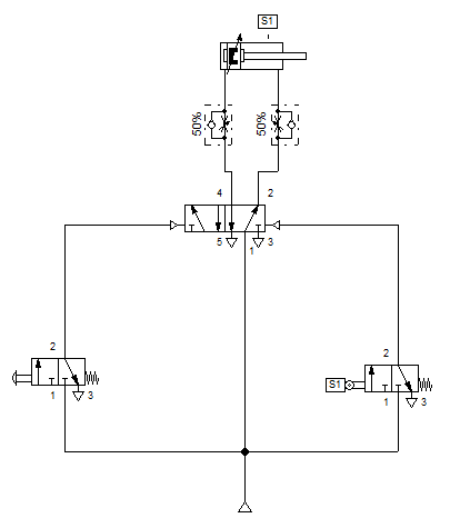
The circuit is built in accordance with indirect control with one key difference is the placement of an acknowledgement sensor. The 5/2 way directional valve, pneumatically actuated, with the sensor provides the memory circuit equivalent in pneumatic. This allows full extension of the double acting cylinder even the push button is release half-way through the process.
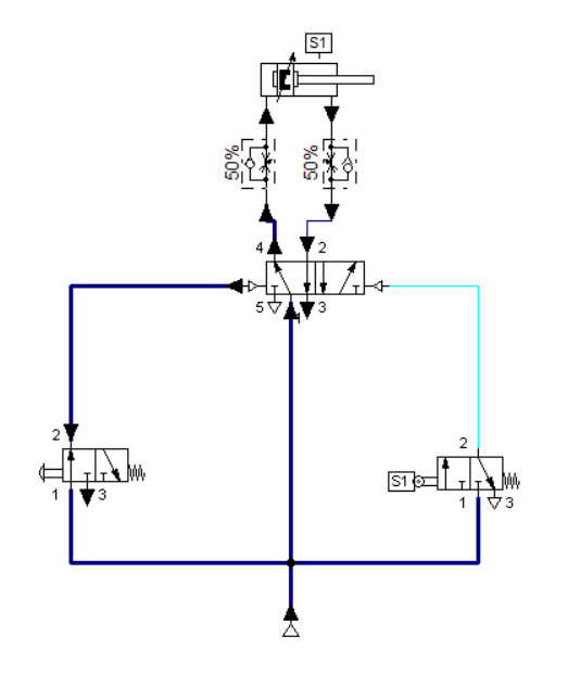
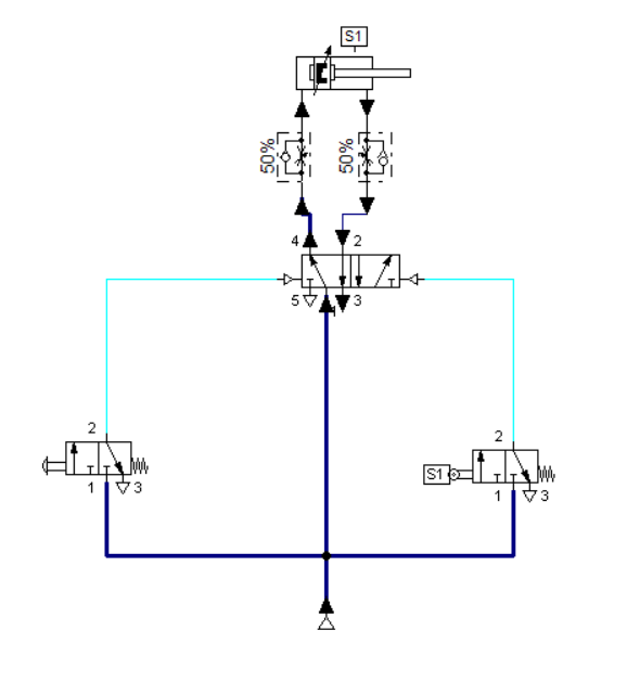
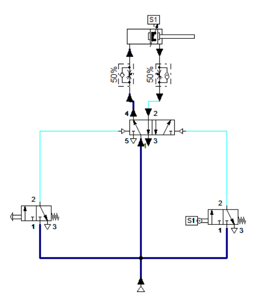
Once the push button is actuated, a signal is applied at port 14 of the 5/2 way directional control valve. The 5/2 way DCV switches from a closed state to an open state across port 1 to 4. The pressure applied at the piston side of the cylinder causes the piston rod to advance and full extend. When the rod reaches the limit switch S1 (sensor), the limit switch S1 is actuated and a signal is transmitted to port 15 of the 5/2 way DCV. This causes the rod to retracts. The speed at which the rod retracts or extend is set by adjusting the flow control valve. After each input 3/2way directional valve (with push button and limit switch) is released, the 5/2 way directional valve has no pressure and returned to initial state. The use of a double pilot on 5/2 way DCV ensures that the switching position does not change.
4. Conclusion
The 5/2-way directional valve with double piloted defined the required memory function. The valve retains its last switched position until an opposing signal is received. This characteristic is independent of the time period, for which the signal is applied to the switching valve. The one way flow control valves control the cylinder speed in both directions and are independently adjustable. Since the displaced air flow is restricted in each case, this is an exhaust air flow control.
5. References
[1] Pneumatic Basic Level. online access
[2] Pneumatic Advanced Level. online access
(Note: All images and diagram in the text are drawn by the author (@juecoree) except those with separate citation.)
If your are Interested in Pneumatic Basics, you can read the other posting:
1. Pneumatic Basics: Direct Control
2. Pneumatic Basics: Indirect Control
3. Pneumatic Basics: AND and OR Logic
Posted with STEMGeeks