Electro-pneumatic Basic: Ejecting a workpiece (Interlocking the sensors)
1. Introduction
In this blog, we present the circuit for the ejecting of workpiece. This blog is a supplement to the previous blog on latching and interlocking. We create a electro-pneumatic circuit that implements the ejecting a workpiece scenario. The scenario is described as:
Using a double-acting cylinder a work piece is removed and tipped onto a conveyor belt. The operation is to be started using a push button. An acknowledgement signal is required when the piston is fully extended, to ensure that the work piece has been tipped onto the belt. The return stroke is to be
automatic.
The task is to set up a sensor that acknowledges the ejection of a workpiece and automatically retract the cylinder once it is done. Similar to the previous post, we elaborate on the interlock and latching mechanism but centered on the sensor. In the next section, the circuit is presented and simulated.
2. Circuit and Simulation

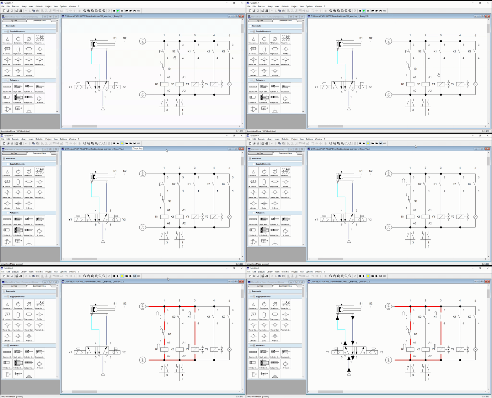
Figure 1: Electro-pneumatic of Ejecting a Workpiece
For the actuation circuit in pneumatics, we used a double acting cylinder, a double solenoid, 5/2-way, limit switches (sensors) and a compressive air. For the electrical control circuit, two relays are used to drive the solenoid Y1 and Y2. I used a 24V power source, a push button, five make switches, two relays, two valve solenoids and an indicator light. The sensors are configured using the distance rule, at which S1 is placed at 0,0 position and S2 at full extension.
Placing the sensor S1 in series with the actuating push button deactivate the actuating push button until the cylinder has returned to initial state after actuation. This serve as the interlock mechanism to sustain the opening of port 4 in double solenoid, 5/2 way DCV. Without those interlocking sensor, the extending cylinder prematurely retracts.

When the push button in Figure 1 is pressed, the current passed and activated the relay coil K1. This sends a signal to open all closed latching contacts K1 or closed normally open contacts. When the contact closed, it energizes the solenoid Y1 which eventually activate the 5/2-way DCV.

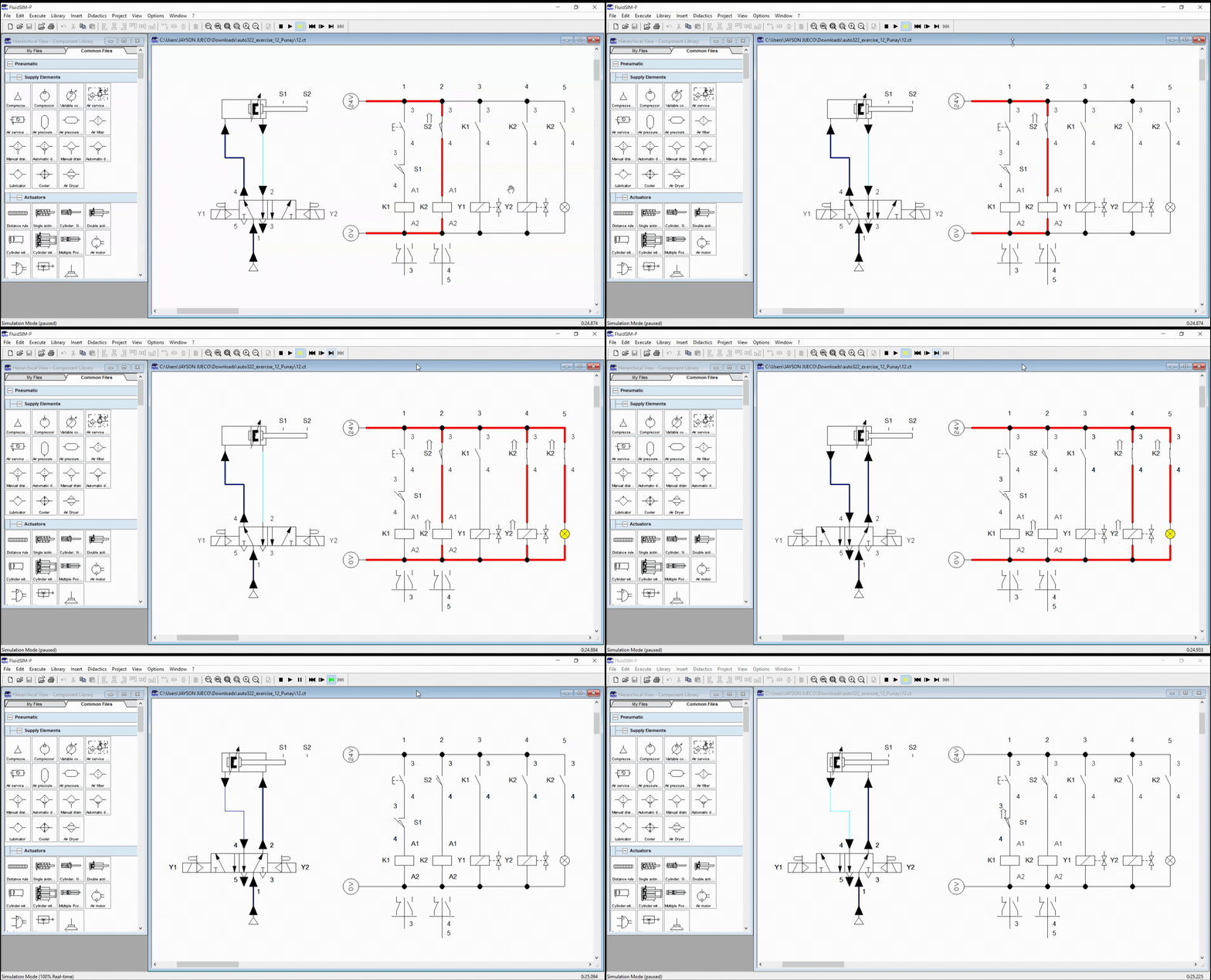
The actuated valve drives the double-acting cylinder to extend as Y1 is energized. The piston continued to extend even after the push button is released. When it has fully extended, the sensor S2 detected the piston and transmitted a signal to activate relay coil K2.

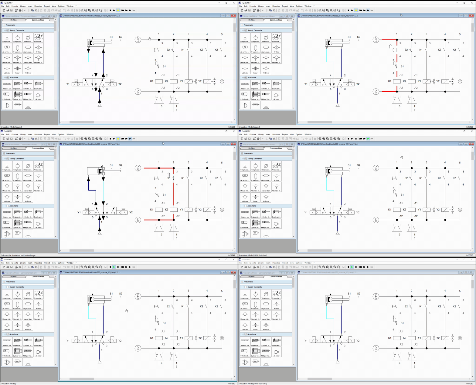
Latched contacts K2 switched from closed contacts to open or in reverse. This allowed current to flow through the solenoid Y2 and activate it. Solenoid Y2 actuated the 5/2-way DCV and allowed air to flow at the retraction port of the cylinder. Also, activation of relay contacts K2 turns on the light to signal that the piston has fully extended. The full simulation is shown below.

Full Simulation
3. Conclusion
In this blog, we elaborated the interlock and latch as to the placement of sensors in the control circuit. As shown in the figure, sensor 1 is deliberately put in series with actuating push button. The interlock mechanism sustained the opening of port 4 in double solenoid, 5/2 way DCV. This eventually prevent the double-acting cylinder to prematurely retracts.
4. References
[1] Pneumatic Basic Level. online access
[2] Pneumatic Advanced Level. online access
[3] Electro-pneumatic Basic Level. online access
(Note: All images and diagram in the text are drawn by the author (@juecoree) except those with separate citation.)
If your are Interested in pneumatic and electro-pneumatic system, you can read:
1. Pneumatic Basics: Direct Control
2. Pneumatic Basics: Indirect Control
3. Pneumatic Basics: AND and OR Logic
4. Pneumatic Basics: Memory Circuit and Speed Control
5. Pneumatic Basics: Dependent control
6. Pneumatic Basics: Multiple Actuators
7. Electro-pneumatic Basic: AND and OR Logic
8. Electro-pneumatic Basics: Interlocking, Latching and XOR logic
9. Electro-pneumatic Basics: Distribution of Workpiece
Posted with STEMGeeks