Drafting Tools: Scales
When creating a digital model using computer-aided drafting, the proper technique is to create the model at full scale. If that model is to be printed as plans on paper, it needs to be sized to fit with room for dimensions, alternate views, notes, callouts, and other elements required for working drawings with enough clarity to fully describe it.
This usually means representing the object or structure in question as larger or smaller than it is intended to be. The ratio is the scale of the drawing, and is chosen according to one of several standards in common use.
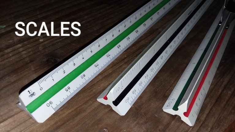
The conventions for these scales are a continuation of methods used in the days when plans were all drawn by hand, and scale calculations had to be performed while creating the drawings. Tools like those shown here were used to create those drawings. Since the measurements are already calculated, they can be directly read to measure out a drawing as it is made, or to read poorly-dimensioned plans.
I should note that professional drawings almost always include notes along the lines of, "do not scale drawings." Ideally, plans are fully dimensioned, so using scales should not be necessary. Every measurement should be clearly shown, or readily derived from the included dimensions. Plans are considered legal documents, and any ambiguity should be handled by contacting the designer. Further, any error in the printing process or misreading of the scale can throw off the reading. That said, ideals often get tossed aside when the real world gets in the way.
Metric Scale
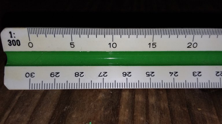
If you live in a country that only uses science units instead of leftover fractional nuttery, this puppy might be all you need. Mine is from Alvin, model no. 742 PM, Metric Architect. Its sides are marked with ratios: 1:100, 1:200, 1:250, 1:300, 1:400, and 1:500. Of course, decimal systems being what they are, this covers your needs for measuring anything from fractions of a millimeter to multiple kilometers depending on the needs of the drawing. Match the ratio, match units, and you're set. Easy-peasy.
Engineer's Scale
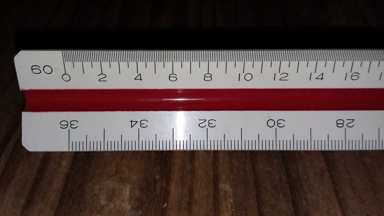
Metric doesn't have a monopoly on decimalization. Mechanical and civil engineers also use a scale with multiples of 10. My engineer's scale is a Pro/Art 160-34. The sides are marked 10, 20, 30, 40, 50, & 60, representing the number of divisions per inch.
Like the Metric scale, these divisions could represent a range of measurements. As such, the 10 scale might be used for any of the following:
- 1" = 1"
- 1" = 1'
- 1" = 10'
- 1" = 100'
The 20 scale is often used for half-sized (1:2) mechanical drawings, while the 50 scale is popular in civil engineering to draw subdivision plat maps where 1 inch might equal 500 feet.
Architect's Scale
Here we go. Were you tired of all those boring multiples of ten? Did you weary of seeing just one scale per edge? Here is your reprieve. Welcome to the glorious insanity that is the Architect's Scale!
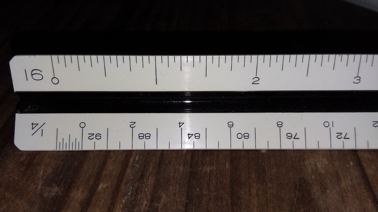
Mine is a Pickett 235 AM. It has the same six sides as the other two, but has a total of ten different scales!
How is this possible?
While scales from different companies may differ slightly, and some may have even eleven options, they all will share one general feature: two scales read from opposite ends of the same side, with one twice the increments of the other.
In the image above, you can see the top edge labeled with a 16. This is a standard ruler divided into 1/16" increments, and is usually read at 1:1 like an ordinary ruler. On the bottom, you can see a 1/4 label, meaning it is set to 1/4"=1', or 1:48 scale. The extra-small increments on the far left are subdivisions of a foot, and the more widely-spaced long lines represent one-foot steps ascending to the right. But there are also shorter lines in between with descending numbers from the right. That is because the other end is marked 1/8, and measures 1/8"=1', or 1:96 scale.
Who needs decimals? We have fractions! Much more fun!
And even better, look at those marks. There aren't 12 divisions per foot, only 8. Those aren't inches, but 1-1/2" ticks! I don't like that. I don't like that at all. Some scales may have marks for each inch or every two inches, but this example I own just makes things extra-difficult.
On the other hand, this one has a bonus 50 scale like the engineer's scale, so it can serve double-duty if you handle a lot of civil engineering plat maps.
The full list of scales on this particular tool is as follows:
- 16 (12" ruler divided into 1/16" increments)
- 50 (engineering scale)
- 1/4 & 1/8
- 3/8 & 3/4
- 1/2 & 1 (1"=1')
- Half (with 1/16" divisions) & Full (with 1/32" divisions)
I think some have a 1-1/2"=1' & 3"=1' scale instead of the 50 on mine.
Most of these are used in the same way, making sure to read from the correct end and not mix up numbers. The line segment (or two points) being measured are located along the scale. If there is not an even number of units, the scale is read from the nearest full mark past the zero and into the smaller tick marks at the end to read off the excess inches.
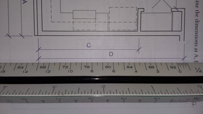
Pictured here is a test problem from my old textbook (Engineering Drawing and Design, 3rd Edition, Delmar Drafting Series, Thompson Learning, page 95) showing a measurement of dimension D using the 1/4"=1' scale. It's a bit distorted by the close-up camera lens, but it should read 13'-9" by my scale. It could be 13'-8" if the fine measurement end were divided into one or two inch divisions, though. Seriously, when in doubt, contact the architect or engineer who produced the plans if it matters that much. This is why you don't scale the drawing if you need absolute precision!
Bonus Tip
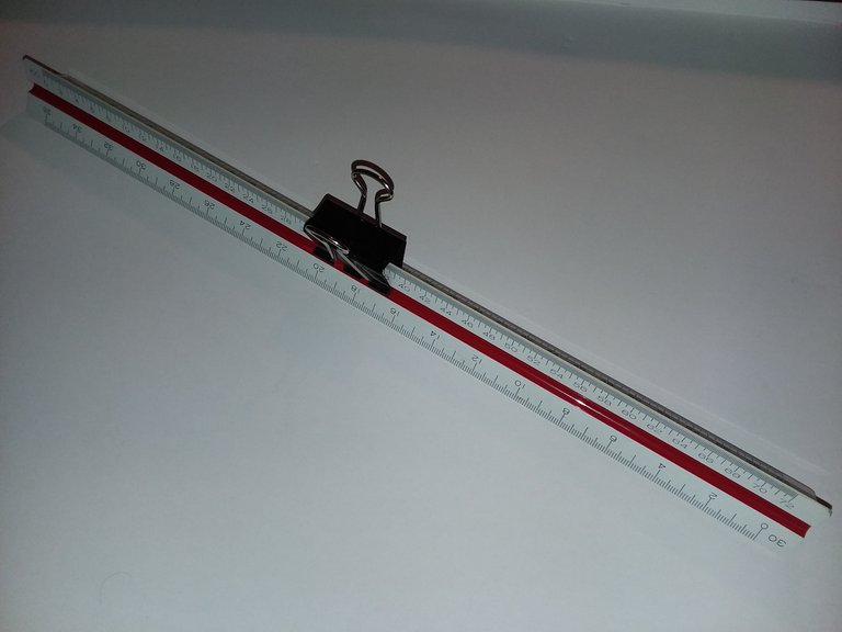
Even with only six options, it's easy to bump your scale and lose your side for measurement. This is even worse with the architect's scale where you need to remember which end to use, too. Use a binder clip to mark the top of your scale so you don't have to hunt as much every time you pick it up! This is a huge help in addition to remembering which stripe to look for if yours is color-coded like mine. Hopefully this hack saves you some time and frustration!
Conclusion
Thanks for reading though this long post about my old drawing tools! You can read my previous post about dividers and compasses here. If you have any questions or additional input, or if I royally screwed up my explanations, chime in below! Hopefully I can continue adding to this series over time as I go through my drafting kit, and eventually I may even show how I would use all these tools to draw something by hand.
Note also that while all three of my personal scales are triangular, other shapes with fewer measurements do exist. If you have something different, share some pictures of your scales, too!


The architect one would have me tripping trying to measure things.
The architect one would have me tripping trying to measure things.
Thanks for the binder clip tip. Wish I had thought of that 40 years ago!
My pencil point is larger than the thing i want to draw (at scale)
what do i do?
You'll have a heck of a time making it. That's for the realm of digital drawings and nanotechnology manufacturing.
Thanks for posting directly within the Free Speech Community again @jacobtothe … We welcome all types of expression.
Have an interesting day.
Ciao
👋 Hi @jacobtothe, I was flipping through the blockchain and stumbled on your work! You've been upvoted by Sketchbook / a community for design and creativity. Looking forward to crossing paths again soon.
✅ Join the Sketchbook Community