Description of some tools used in directional drilling for oil well construction
Greetings to my dear friends and followers of the hive platform, especially to all those who love STEM content.
On this occasion I want to present this post where I will make a full description of the tools used in directional drilling with an engineering approach, taking into account that without many of the tools used for directional drilling is impossible to apply this technique.
Among the variability of equipment used in well drilling it is important to highlight the value of being able to understand the main objective of well drilling, as I explained in previous posts the basic objective of directional drilling is to be able to build an oil well where at some point in its trajectory it has to make a deviation from its verticality.
The deviation of the well to deserve to have a control in the drilling of the well as we intend to divert its direction, for this is of great help a team called mud motor, this tool will explain its basic principle of action, how it helps to build the hole in a directional way, the advantages and disadvantages for the oil industry.
It is also important to explain the directional tools that measure certain directional parameters in real time, so I can say that basically the development of this post will focus on the description of the motor mud and the measurements made during the directional drilling of the well.
Mud Motor
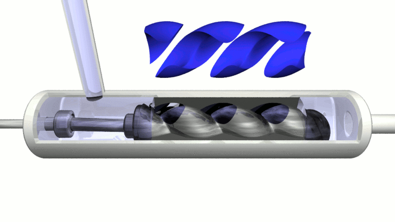
The mud motor is also called a drilling motor whose basic principle of action is to operate as a progressive cavity positive displacement pump (PCPD). In order to have a clear idea of the operational meaning of a progressive cavity positive displacement pump, it is essential that we observe the operation of the following animated image which gives a basic idea of how this progressive cavity positive pumping mechanism works:
The idea of this pump is to take advantage of the drilling fluid (drilling mud) that is pumped from the mud tanks to the bottom of the well, so that it reaches the bottom of the well it has to circulate inside the drill string, when passing inside the drill string it also passes inside this progressive cavity pump, The circulation of drilling mud inside this pump makes the small cavities of the pump turn, so the rotor turns in order to make the drill bit turn without the top drive on the surface having to turn to make the string turn, so drilling can be done in a more controlled way and the directional section of the well can be carried out with more control.
The way the progressive cavity positive displacement pump uses the drilling mud is intended to generate an eccentric motion in the power portion of the pump motor, and all of this rotational power is transmitted to the drill string.
In its path the mud motor needs to have different configurations in the positioning of the rotor and the stator, all with the objective of obtaining an optimized performance in the directional drilling of the well. It is important to mention that the power of rotation of the drill string as a result of the power provided by the PCPD pump is not the same as when the drill string is rotated by the top drive, however the circulation energy of the drilling mud inside the PCPD pump makes the drill string able to rotate between 60 to 100 revolutions per minute (RPM).
Basic principle of action of the mud motor
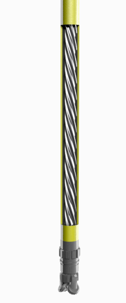
There is a basic principle of operation of the mud motor, and it is the principle that the helical rotor it has internally will help it rotate eccentrically only when the following condition is met:
The stator must contain more lobes than the rotor.
The drilling fluid, also called drilling mud, will circulate inside the motor, generating a power transmission that results in the motor assembly rotating, while at the same time the motor rotates the drill bit.
.gif)
How is the construction of the hole with the use of the mud motor?
Perhaps it could be thought that the use of the motorized mud is only in the sections in which the oil well is constructed in a directional way, however in vertical holes the motorized mud can also be used but it would not be so economically profitable speaking even though it can provide us with an increase in the drilling speed (ROP).
As one of the objectives of this post is to show and explain the use of some of the most commonly used equipment in directional drilling, it is based on this point that I can affirm that the greatest use of this equipment is in directional drilling, although it is important to mention that not only with the motor mud can we guide the drill string to reach the producing reservoir in the construction of the well, however by using other tools more time is consumed in building the well increasing the drilling costs.
More traditional mud motors can be modified from 0 degrees to 4 degrees with approximately six increments of deviation per degree of bend.
What determines the amount in the degree of bend of the motor?
The amount of curvature is determined by the rate of climb necessary to reach the target zone, i.e. depending on how fast we want to continue drilling we must change the amount in the degree of motor curvature.
By using a Measurement While Drilling (MWD) tool, the directional drill can direct the drill string to the desired target zone (producing reservoir).
In conclusion there are multiple variables in the use of the motor mud to drill in a directional way, however among the most important are the flow rate of the drilling mud, because as the flow rate is higher, at the same proportion will be higher revolutions per minute of the drill bit, as mentioned the degree of curvature is also influential, finally the internal configuration of the motor mud is also influential for the directional control in the construction of the well.
Measurement while drilling
The first important thing is to accept that in directional drilling, the use of the motor mud would be useless without the constant intervention of some measurement during the drilling denoted by its acronym in English as MWD.
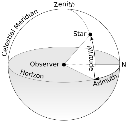
The tools used that involve measurements during drilling are capable of providing real-time directional surveys, since these tools have a set of accelerometers and magnetometers that help measure the inclination and azimuth of the well, very important in the construction of the directional part of the well.
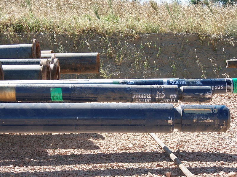
Generally there are wells that when they are being built the directional part is in the phase of the intermediate hole, so any error can imply the loss in the construction of the well, all this I mention is because the MWD tools have certain mechanical benefits in the transmission of data where without having to take all the drill string to the surface to see the conditions in which the fuse is.
The use of all this information allows the directional driller a more efficient way to drill and build the directional part, the mechanical information obtained also helps all tools to operate within the range of their technical specifications.
With this article it becomes completely clear that directional drilling requires many elements that are key in the construction of an oil well in its directional path, such as the mud motor and measurement during drilling.
With the implementation of the mud motor we optimize the drilling parameters, and when we combine this with the benefits provided by MWD tools we obtain the necessary requirements for directional drilling to end up being an experience where the final results are the construction of a hole according to the proposed design.
References consulted and recommended
Thanks for your contribution to the STEMsocial community. Feel free to join us on discord to get to know the rest of us!
Please consider supporting our funding proposal, approving our witness (@stem.witness) or delegating to the @stemsocial account (for some ROI).
Please consider using the STEMsocial app app and including @stemsocial as a beneficiary to get a stronger support.