College Assignment About Oscilloscope
Note
This is my undergraduate assignment that I translated to English myself (Bahasa Indonesia dibawah / Indonesian Below) in the Electrical Measurement course where the task is to write an essay on Oscilloscopes. This assignment has never been published anywhere and I, as the author and copyright holder, license this assignment customized CC-BY-SA where anyone can share, copy, republish, and sell on condition to state my name as the author and notify that the original and open version available here.
Chapter 1 Introduction
1.1 Background
Have you ever seen a line drawing that goes up and down, up and down again? Have you ever heard of signals, waves, vibrations, alternating current (AC)? Maybe on television you have seen the form of a signal displayed by news or educational media. Maybe you don't know the measuring instrument that can display the wave image. The measuring instrument is called an oscilloscope.
1.2 Objective
- Know the term Oscilloscope.
- Know the basic circuit of the Oscilloscope.
- Identifying the outside (buttons) of the Oscilloscope.
- Know the basic ways of using the Oscilloscope.
- Get to know the various uses of the Oscilloscope.
1.3 Scope of Material
- Understanding oscilloscope.
- Basic oscilloscope diagram.
- Buttons on the Oscilloscope.
- An introduction to measurements on an oscilloscope.
- Oscilloscope applications in the outside world.
Chapter 2 Basic Theory
2.1 Vibration
The vibrations can be in the form of up and down, left-right, left side - right side, back and forth. In life we feel vibrations are a continuous back and forth motion, for example earthquakes.
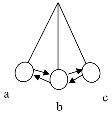
Movement of the pendulum from a to c back again to a or a > b > c > b > a is said to be 1 vibration.
2.2 Frequency
Frequency is defined as the number of vibrations that are carried out every second. The unit of frequency in the International System is hertz, abbreviated as Hz. This name is taken from the last name from the figure of Physics, whose name is Heinrich Hertz.
hertz = vibration/second, frequency = vibration/time
2.3 Period
Period is the time it takes to perform 1 vibration.
f swing takes 1 second,
2f swing takes 2 seconds,
100f swing takes 100 seconds,
f/2 swings take 1/2 second,
f/100 swings take 1/100 of a second,
f/f=1 swing, takes 1/f second,
T = 1/f
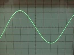
2.4 Wave
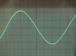
Waves are described as vibrations up and down.
Chapter 3 Discussion
3.1 What is an oscilloscope?
An oscilloscope is an electronic device that can provide an image on the screen (display) of the electrical signal connected to its input. Oscilloscopes usually have an input signal gate and an output signal. Oscilloscopes generally display images in 2 dimensions, the screen is in boxes. There are also 3 dimensions. A wave is converted into electricity, after which it can be read on an oscilloscope. With an oscilloscope it is possible to see the shape of the wave equation of an electrical signal.
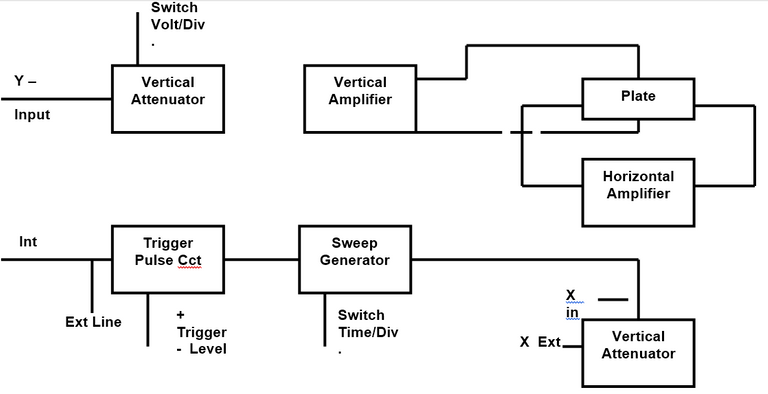
3.2 How is the basic circuit of an oscilloscope?
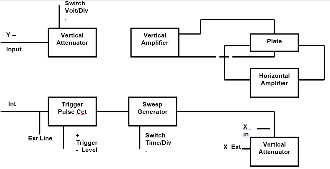
Oscilloscope Circuit
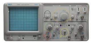
3.3 Name the buttons on the Oscilloscope?
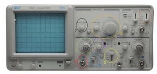
The external physical parts of the oscilloscope.
- Circle 1 represents the signal source (CH1, CH2, LINE, and EXT).
- Circle 2 represents Channel 1 input.
- Circle 3 indicates which channel is displayed on the screen (CH1, CH2, DUAL, and ADD).
- Circle 4 represents the input signal type (AC, GND, and DC).
- Circle 5 represents Volts/Div.
- Circle 6 indicates Vertical Position.
- Circle 7 represents Horizontal Position.
- Circle 8 represents Time/Div (time per square on the oscilloscope screen).
- Grid screen (boxes), the lines of the squares, either horizontal or vertical, are called divs.
3.4 How to basically use it?
An explanation for the schematic of the analog oscilloscope working principle:
- When we connect a probe to a circuit, a voltage signal flows from the probe to the vertical arrangement of an oscilloscope system (Vertical System), an Attenuator will attenuate the input voltage signal while the Amplifier will amplify the input voltage signal. This setting is determined by us when moving the "Volt/Div" knob on the Oscilloscope user interface.
- The voltage that comes out of the vertical system is then forwarded to the vertical deflection plate on a CRT (Catode Ray Tube), the voltage signal that is inserted into this plate will later be used by the CRT to move the electron beams in a vertical plane only (up or down).
- Up to this point, it can be concluded that the Vertical System on an analog oscilloscope functions to adjust the amplitude appearance of the observed signal.
- Then the signal enters the vertical deflection plate. The voltage signal applied here causes the electron beams to move. A positive voltage causes the electron beam to move upwards, while a negative voltage causes the electrons to be pushed down.
- The signal that comes out of the Vertical System is also directed to the Trigger System to trigger the sweep generator to create what is called a "Horizontal Sweep", namely the movement of electrons in a sweep - sweeping left and right - in a horizontal dimension or in other words, an expression for the action that causes electrons to move very quickly across the screen in a certain time interval. The movement of electrons is very fast (can reach 500,000 times per second) which causes the electrons to appear as lines on the screen (for example, like a fan on a fan that looks like a circle when it rotates).
- This setting of the number of times the electrons move across the screen is what we can think of as the Period/Frequency setting that appears on the screen, the concrete form is when we move the Time/Div knob on the Oscilloscope.
- Arrangement of the vertical and horizontal planes together finally can represent the observed voltage signal in the form of a graph that we can see on the CRT screen.
3.5 How is the application of the oscilloscope?
Some of the oscilloscope functions include::
- Measure the amount of voltage and its relationship to time.
- Measures the frequency of the oscillating signal.
- Checks the path of a signal on an electrical circuit.
- Differentiate between AC and DC currents.
- Determines the noise in an electrical circuit.
- Used in the engineering industry.
- Used in the scientific field.
- Used in the telecommunications sector.
Chapter 4 Closing
4.1 Conclusion
An oscilloscope is a device that displays electrical signals in the form of waves. Oscilloscopes are used in various fields. Provided that something can be defined in the form of waves.
Tugas Kuliah Tentang Osiloskop
Catatan
Ini merupakan tugas S1 saya di mata kuliah Pengukuran Listrik dimana tugasnya adalah menulis essai mengenai Osiloskop. Tugas ini tidak pernah dipublikasi dimanapun dan saya sebagai penulis dan pemegang hak cipta melisensi tugas ini customized CC-BY-SA dimana siapa saja boleh membagi, menyalin, mempublikasi ulang, dan menjualnya dengan syarat mencatumkan nama saya sebagai penulis dan memberitahu bahwa versi asli dan terbuka tersedia disini.
BAB 1 Pendahuluan
1.1 Latar Belakang
Pernahkah anda melihat bentuk gambar garis yang naik-turun, naik lagi dan turun lagi? Pernahkah anda mendengar mengenai sinyal, gelombang, getaran, arus listrik bolak-balik (Alternating Current (AC))? Mungkin di televisi anda pernah melihat bentuk sinyal yang ditampilkan berita atau media edukasi. Mungkin anda belum mengetahui alat ukur yang dapat menampilkan gambar gelombang tersebut. Alat ukur tersebut disebut Osiloskop.
1.2 Tujuan
- Mengenal istilah Osiloskop.
- Mengetahui rangkaian dasar Osiloskop.
- Mengenal bagian luar (tombol-tombol) Osiloskop.
- Mengetahui cara dasar menggunakan Osiloskop.
- Mengenal berbagai macam kegunaan Osiloskop.
1.3 Ruang Lingkup Materi
- Pengertian Osiloskop.
- Diagram dasar Osiloskop.
- Tombol-tombol pada Osiloskop.
- Pengenalan pengukuran pada Osiloskop.
- Applikasi Osiloskop di dunia luar.
BAB 2 Dasar Teori
2.1 Getaran
Getaran dapat berupa naik-turun, kiri-kanan, samping kiri – samping kanan, maju-mundur. Dalam kehidupan yang kita rasakan getaran adalah gerakan bolak-balik terus menerus, contohnya gempa bumi.

Gerakan bandul dari a ke c balik lagi ke a atau a > b > c > b > a dikatakan 1 getaran.
2.2 Frekuensi
Frekuensi diartikan sebagai banyaknya getaran yang dilakukan setiap detik. Satuan frekuensi dalam SI (Sistem Internasional) adalah hertz, disingkat Hz. Nama ini diambil dari nama belakang tokoh Fisika, yang bernama Heinrich Hertz.
hertz = getaran/detik, frekuensi = getaran/waktu
2.3 Periode
Periode adalah waktu yang diperlukan untuk melakukan 1 getaran.
f ayunan membutuhkan waktu 1 detik,
2f ayunan membutuhkan waktu 2 detik,
100f ayunan membutuhkan waktu 100 detik,
f/2 ayunan membutuhkan waktu 1/2 detik,
f/100 ayunan membutuhkan waktu 1/100 detik,
f/f = 1 ayunan, membutuhkan waktu 1/f detik,
T = 1/f
2.4 Gelombang
Gelombang digambarkan seperti getaran yang naik-turun-naik-turun.
BAB 3 Pembahasan
3.1 Apa itu Osiloskop?
Osiloskop merupakan suatu peralatan elektronik yang dapat memberikan gambar pada layarnya (display), dan sinyal listrik yang dihubungkan pada inputnya. Osciloscope biasanya mempunyai gerbang sinyal input dan sinyal output. Osciloscope umumnya menampilkan gambar dalam 2 dimensi, layarnya kotak-kotak, adapun yang 3 dimensi. Suatu gelombang di konversi menjadi listrik, setelah itu dapat dibaca pada osciloscope. Dengan osiloskop memungkinkan untuk melihat bentuk dari persamaan gelombang suatu sinyal listrik.
3.2 Bagaimana rangkaian dasar Osiloskop?
Rangkaian Osiloskop
3.3 Sebutkan tombol-tombol pada Osiloskop?
Bagian-bagian fisik luar osiloskop.
- Lingkaran 1 menyatakan sumber signal (CH1, CH2, LINE, dan EXT).
- Lingkaran 2 menyatakan input Channel 1.
- Lingkaran 3 menyatakan channel mana yang ditampilkan pada layar (CH1, CH2, DUAL, dan ADD).
- Lingkaran 4 menyatakan jenis signal input (AC, GND, dan DC).
- Lingkaran 5 menyatakan Volts/Div.
- Lingkaran 6 menyatakan Vertical Position (posisi secara vertikal).
- Lingkaran 7 menyatakan Horizontal Position (posisi secara horizontal).
- Lingkaran 8 menyatakan Time/Div (waktu per kotak pada layar osiloskop).
- Layar grid (kotak-kotak), garisnya kotaknya baik garis horizontal ataupun vertical disebut div.
3.4 Bagaimana cara menggunakannya (dasar saja)?
Penjelasan untuk skema prinsip kerja osiloskop analog:
- Saat kita menghubungkan probe ke sebuah rangkaian, sinyal tegangan mengalir dari probe menuju ke pengaturan vertikal dari sebuah sistem osiloskop (Vertical System), sebuah Attenuator akan melemahkan sinyal tegangan input sedangkan Amplifier akan menguatkan sinyal tegangan input. Pengaturan ini ditentukan oleh kita saat menggerakkan kenop "Volt/Div" pada user interface Osiloskop.
- Tegangan yang keluar dari sistem vertikal lalu diteruskan menuju pelat defleksi vertikal pada sebuah CRT (Catode Ray Tube), sinyal tegangan yang dimasukkan ke pelat ini nantinya akan digunakan oleh CRT untuk menggerakkan berkas-berkas elektron secara bidang vertikal saja (ke atas atau ke bawah).
- Sampai point ini dapat disimpulkan bahwa Vertical System pada osiloskop analog berfungsi untuk mengatur penampakan Amplitudo dari sinyal yang diamati.
- Selanjutnya sinyal masuk ke dalam pelat defleksi vertikal. Sinyal tegangan yang teraplikasikan disini menyebabkan berkas-berkas elektron bergerak. Tegangan positif mengakibatkan berkas elektron bergerak ke atas, sedangkan tegangan negatif menyebabkan elektron terdorong ke bawah.
- Sinyal yang keluar dari Vertical System tadi juga diarahkan ke Trigger System untuk memicu sweep generator dalam menciptakan apa yang disebut dengan "Horizontal Sweep" yaitu pergerakan elektron secara sweep - menyapu ke kiri dan ke kanan - dalam dimensi horizontal atau dengan kata lain adalah sebuah ungkapan untuk aksi yang menyebabkan elektron untuk bergerak sangat cepat menyeberangi layar dalam suatu interval waktu tertentu. Pergerakan elektron yang sangat cepat (dapat mencapai 500,000 kali per detik) inilah yang menyebabkan elektron tampak seperti garis pada layar (misalnya seperti daun kipas pada kipas angin yang tampak seperti lingkaran saja saat berputar).
- Pengaturan berapa kali elektron bergerak menyebrangi layar inilah yang dapat kita anggap sebagai pengaturan Periode/Frekuensi yang tampak pada layar, bentuk konkretnya adalah saat kita menggerakkan kenop Time/Div pada Osiloskop.
- Pengaturan bidang vertikal dan horizontal secara bersama-sama akhirnya dapat merepresentasikan sinyal tegangan yang diamati ke dalam bentuk grafik yang dapat kita lihat pada layar CRT.
3.5 Bagaimana applikasi pada Osiloskop?
Beberapa fungsi osiloskop antara lain untuk:
- Mengukur besar tegangan listrik dan hubungannya terhadap waktu.
- Mengukur frekuensi sinyal yang berosilasi.
- Mengecek jalannya suatu sinyal pada sebuah rangkaian listrik.
- Membedakan arus AC dengan arus DC.
- Mengetahui noise pada sebuah rangkaian listrik.
- Digunakan pada industry teknik.
- Digunakan pada bidang sains.
- Digunakan pada bidang telekomunikasi.
BAB 4 Penutup
4.1 Kesimpulan
Osiloskop adalah suatu alat yang menampilkan sinyal listrik dalam bentuk gelombang. Osiloskop digunakan diberbagai bidang. Asalkan sesuatu tersebut dapat didefinisikan dalam bentuk gelombang.
4.2 Literature Review
- http://www.sisilain.net/2010/10/pengertian-osiloskop.html
- http://joe-proudly-present.blogspot.com/2010/11/osiloskop-analog.html
- http://www.sentra-edukasi.com/2009/06/materi-elektro-osiloskop-oscilloscope.html
- http://web.ipb.ac.id/~henrymanik/pdf/Tutorial%20OSILOSKOP.pdf
- Getaran dan Gelombang, 2009, Prof. Yohanes Surya, Ph.D
- MODUL PRAKTIKUM PENGUKURAN LISTRIK TEKNIK ELEKTRO UNIVERSITAS UDAYANA
- http://en.wikipedia.org/wiki/Oscilloscope
Mirror
- https://www.publish0x.com/fajar-purnama-academics/college-assignment-about-oscilloscope-xpnneyw?a=4oeEw0Yb0B&tid=hive
- https://0fajarpurnama0.github.io/bachelor/2020/08/06/oscilloscope-college-assignment
- https://0fajarpurnama0.medium.com/college-assignment-about-oscilloscope-efc15688702c
- https://hicc.cs.kumamoto-u.ac.jp/~fajar/bachelor/oscilloscope-college-assignment
- https://0darkking0.blogspot.com/2020/12/college-assignment-about-oscilloscope.html
- https://0fajarpurnama0.cloudaccess.host/index.php/9-fajar-purnama-academics/165-college-assignment-about-oscilloscope
- http://0fajarpurnama0.weebly.com/blog/college-assignment-about-oscilloscope
- https://0fajarpurnama0.wixsite.com/0fajarpurnama0/post/college-assignment-about-oscilloscope
- https://read.cash/@FajarPurnama/college-assignment-about-oscilloscope-9d9af1ab
- https://www.uptrennd.com/post-detail/college-assignment-about-oscilloscope~ODQxMjc1