Ampacity Calculation
Ampacity: The maximum current, in amperes, that a conductor
can carry continuously under the conditions of use without
exceeding its temperature rating.
In this post, we are going to take a glance at how to calculate one of the most important properties concerning electrical conductors, The Ampacity. For that, we are going to make use of the National Electrical Code (2017) used in the United States, our focus will stand at low voltage systems (until 1000 V). Besides, it will be some details related to other steps to take into account when an electrical conductor is chosen.
The task is to choose a caliber, material, and insulator for the conductor or conductors that will go along with the electrical conduit. Here, we have split this objective into two branches: "Getting the data" and "Steps to follow".
Getting the data
Number of Threads that feed the load.
The loads can be fed according to the number of phases (p) and if there is or not a neutral (n). These, along with the ground conductor are called threads. Thus, we have the following options about how many threads can take place feeding the load (we don't take into account the ground wire because it doesn't feed the load with electrical power).
1 phase -> Two threads -> 1p + 1n
1 phase -> three threads -> 2p + 1n (balanced or unbalanced)
3 phases -> three threads -> 3p
3 phases -> four threads -> 3p + 1n (balanced or unbalanced )
Current consumed by the load.
This is the nominal current in Ampers consumed for the load.
The Load is either "continuous in time" or "no continuous in time".
When a load is operated for 3 hours or more at its nominal current is have to be considered "continuous" otherwise is "discontinuous"
Ambient Temperature.
This is important data. When the ambiente temperature rises the conductor reduces its capacity to conduct current and its internal temperature rise too, as a result, the voltage drop in the system is increased. This temperature can be measure using optical thermometers into the space that assemble the conductors.
Will the conductors be exposed to the sunlight?
The (US) National Electric Code (2017) states
Raceways and Cables Exposed to Sunlight on Rooftops. Where
raceways or cables are exposed to direct sunlight on or above
rooftops, raceways or cables shall be installed a minimum
distance above the roof to the bottom of the raceway or cable
of 23 mm (7∕8 in.). Where the distance above the roof to the
bottom of the raceway is less than 23 mm (7∕8 in.), a temperature
adder of 33°C (60°F) shall be added to the outdoor
temperature to determine the applicable ambient temperature
for application of the correction factors in Table
310.15(B)(2)(a) or Table 310.15(B)(2)(b).
The number of conductors in the conduit.
How many conductors are staked into a conduit? This number is computed knowing how many loads or electrical boards are going to be feed through this conduit. Besides, we have to know the transversal section of each conductor and the transversal section of the conduit in [m^2]. Using these numbers it will be calculated the "stacking-factor"
Also, it is important to consider a number o possibles conductors to be staked for future loads and electric boards.
The Staking-Factor establish the relation between the cross-section that will be occupied by the conductors and the área of the conduit, can be calculated with the next formula
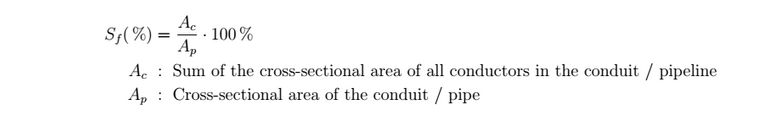
And it has to satisfy
| Number of conductors | Stacking-Factor [%] |
|---|---|
| 1 | 53 |
| 2 | 31 |
| >2 | 40 |
Length of the conduit.
If the length of the conduit is bigger than 60 cm it has to be considered the data in point 6. Otherwise, it will not be necessary (nevertheless the case has to be studied).
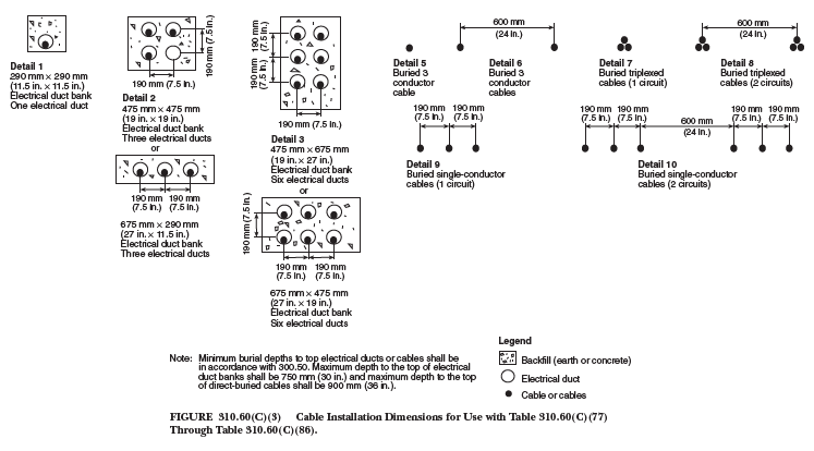
Kind of ground which the conduits will pass.
Depending on the ground, the design of the conduit o conduits can be different. For further and more complex calculations it would be helpful to know the Soil resistivity. For further information about underground conductors' disposition, we have the next image from page 155 in the NEC (2017).
The temperature in the terminals.
As a rule, the max temperature operation of the conductor has to be less or equal to the minimum temperature operation at devices connected at the terminals of the conductor.
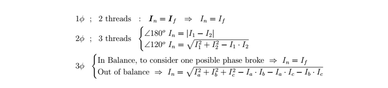
How to calculate the current of the neutral conductor?
The neutral conductor could or not carry current, but it has to be designed in the case it does. This depends on the kind of load. In the next image is shown some formulas to find the module of this current.
Steps to follow
- We have to choose a material and an insulator.
The most common materials in conductors are Copper, Aluminum, or some kind of alloy between them. In the next table, some properties are shown. It is important to know that Aluminum is cheaper than copper.
| Copper | Aluminum | |
|---|---|---|
| Resistivity [(Ohm-mm^2)] | 0.017 | 0.028 |
| Specific Weight [g/cm^3] | 8.9 | 2.7 |
| Tensile Strength [Kg/mm^2] | 55 | 40 |
| melting point [°C] | 1.083 | 660 |
At the moment to choose the insulator for the conductor, we are going to find some terms related to the material associated with its making. The next table could be helpful to understand the terminology.
| Letter | Meaning |
|---|---|
| T | Thermoplastic Insulation |
| N | Nylon Jacket |
| H | Maximum temperature 70 °C |
| HH | Maximum temperature 90 °C |
| W | Use in places saturated with water |
| U | Underground or directly buried |
| UF | Underground Feeder Conductor |
| R | Rubber Insulating cover |
| X | Thermosetting Synthetic Polymer |
| SE | Service Entrance Conductor |
| USE | Underground Service Entrance Conductor |
| A | Asbestos insulation |
| MI | Mineral insulation |
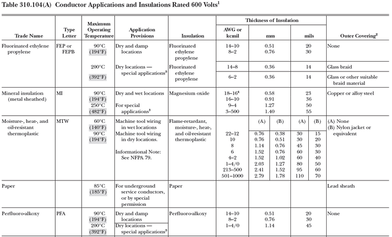
To identify the insulator for a conductor, several combinations are done with these letters depending on its future application. The next example image is an extract from page 166 in the NEC (2017) that helps us to choose the appropriate insulator depending on the ambient.
If the load is "no continues" we are going to consider the 100% of its nominal current for the ampacity calculation, otherwise, if the load is "continues" we are going to consider the 125% for the ampacity calculation.
Now is time to choose one caliber for the conductor, for this we are going to regard the nominal current ( In * 1.0 or In * 1.25 depending on the previous step) and find some caliber in the ampacity tables that meets Ampacity > In. The next image is an extract from pages [150 - 154] in the NEC (2017) where are most of the ampacity tables.
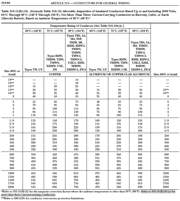
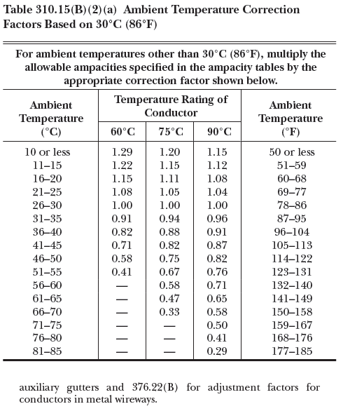
- As you can see, this table is only valid if the conductor's ambient temperature is 30°C and there are not more than three conductors in the conduit (also is restricted to others facts, but we are not going to treat them here). If your system has a different ambient temperature the ampacity has to be modified by some factors according to these necessities. For that, other tables can be helpful.
From page 147 in the NEC (2017) we have the Ambient Temperature Correction Factors Based on 30°C (as we had in our the previous table, there is another table based on 40°C)
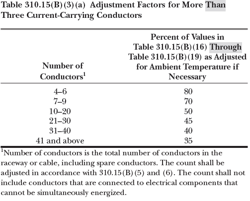
- If your conduit has more than three conductors, then you need to multiply the ampacity for another factor. From page 147 in the NEC (2017) we have the Adjustment Factors for More Than Three Current-Carrying Conductors
- As you can see, the ampacity can be modified so many times that it could no meet the condition Ampacity > In, therefore you have to choose a bigger caliber and repeat the process until a caliber is adjusted to all requirements
There are a lot of other tables in the NEC (2017) for several situations according to ampacity, these are related to the data collected at the beginning of this post and other relevant data. Although is normal only use the tables for these calculations, in the NEC are proposed some formulas to find the ampacity and treat with the ambient temperature. We invited the reader to take a look at the pages we are mentioned here to understand more about this subject. Coming soon we are going to be talking about voltage drop in electrical systems.