Understanding The Physics Behind Our Electromagnetic World.
Nikola Tesla has been described as the man who
invented the twentieth century because of his understanding of electromagnetism
and the applications he evolved that led to the large-scale generation and
distribution of electricity.
Now in the twenty-first century, scientists study the interaction of the magnetic field of the Sun with that of the Earth using data from the Cluster satellites. Not only does this help us understand better the physics of our nearest star but it also helps us predict some of the more damaging effects of large solar flares on the Earth and its near environment.
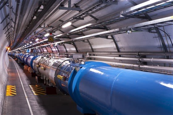
A section of the LHC. Maximilien Brice, CC BY-SA 4.0
In 2008 the Large Hadron Collider (LHC) started its search for the Higgs Boson and a deeper understanding of the fundamental nature of matter. The LHC accelerates beams of protons around a synchrotron ring of 27 km circumference until they reach energies of 7 TeV. To bend protons around this path requires dipole magnets that produce a magnetic field of 8.4 Tesla (that’s about 100 000 times the magnetic field of the Earth). These magnets use superconductors and draw currents of about 11 700 amps. They are 143 metres long and 1232 of them are needed. The LHC uses over 2500 other magnets to guide and collide the proton beams.
This is just a tiny fraction of the billions of electromagnetic devices, including motors and drives, and even down to magnetically controlled nano-rods of gold, nickel and platinum, that require an understanding of electromagnetism.
In this article, I will discuss the inextricable link between moving charges and magnetic fields. When charges move in a circuit the current is surrounded by a complete loop of magnetic field – a loop of electric current surrounded by a loop of magnetic field – each linked with the other. This article will also look at the way current loops create magnetic fields; the next chapter will take care of how changing magnetic loops can create currents.
FIELDS AROUND CURRENTS
If we pass an electric current along a wire and then bring a compass near it, the compass needle (which is a strong magnet) will be deflected. This is because the current has a magnetic field around it, as first demonstrated by Hans Christian Oersted in 1820.
What do we mean by a magnetic field? The compass needle is deflected because it experiences a force. With a constant current, the size of the force depends only on how far the needle is from the wire: the closer it is, the greater the force on the needle – but the needle does not have to touch the wire. The effect, then, acts at a distance. So we describe the space around the wire as containing a magnetic field.
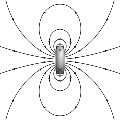
Magnetic dipole. Geek3 - Own work, CC BY-SA 3.0
A magnetic field can be represented by ‘field lines’ that show the shape of the field. We draw the lines close together if we want to show a strong field, and further apart for a weaker field. The field has a direction of action. We define the direction of the field at a point as the direction of the force that would act on an isolated north pole placed there. (So far no-one has ever found such a thing as an isolated north pole – magnetic poles always occur in pairs – but it is a useful idea to help define field directions.) The direction of the magnetic field is from north to south. The Earth has its own magnetic field, which has been used for hundreds of years in navigation. Magnetic field is a vector quantity.
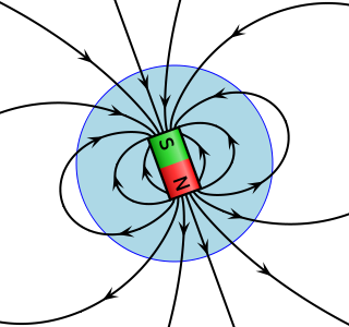
A sketch of Earth's magnetic field. Geek3 - Own work, CC BY-SA 3.0
MAGNETIC FIELD AND FLUX
The idea of field lines was one of Faraday’s important contributions to physics. The patterns we draw around magnets and coils to describe the shape and variation in strength of fields were first used by him. He imagined the field lines passing through a surface, and he called this ‘flux’
The flux Φ is defined as:
flux = field strength × the area it passes through
Φ = BA
If the field is not perpendicular to the area, then the equation becomes
Φ = BA sin θ
Flux is measured in webers (Wb).
The strength of the magnetic field can be defined in terms of flux and is correctly termed the flux density:
flux density, B = Φ/A
Field lines or flux paths are always in complete loops. This is not always obvious when we look at fields around permanent magnets. If we could see the field lines inside the magnet we would be convinced.
Just as we are used to the idea of electric circuits being complete paths or loops (we call them ‘circuits), we can use the idea of magnetic circuits.
MAGNETIC CIRCUITS
In the figure below, the flux is set up by a current flowing through a coil, or solenoid. The flux, represented by the field lines, is in complete loops. This is always the case. In some cases, the loops are set up in the space around and through the coil, while in others, they are contained within a solid core such as ‘soft iron’. We can think of these complete loops as ‘magnetic circuits’.
We know from elementary physics that the physical dimensions of the wire (cross-sectional area and length) in a simple electric circuit affect the current. Similarly, we shall see here that the dimensions of a magnetic circuit affect the flux that can be set up.
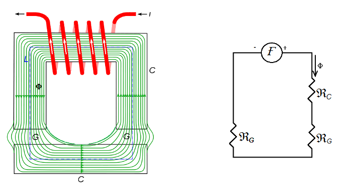
Electromagnet with air gap and magnetic circuit equivalent. Frankemann - Own work, CC BY-SA 4.0
The flux also depends on the size of the current and the number of turns on the coil. Without current and turns of the coil there would be no flux. We say the flux is ‘generated’ by the current turns. If N is the number of turns, I is the current and Φ is the flux, then:
NI α Φ
To understand how the dimensions of the magnetic circuit can affect the flux it is probably easier to think about a transformer. The flux is generated by a primary coil. The iron core has the interesting and useful property of confining nearly all the flux within the core. The physical dimensions of the core, its cross-sectional area and the length all affect the flux.
MAGNETIC CIRCUITS COMPARED WITH ELECTRIC CIRCUITS
At this point it is worth comparing magnetic circuits with simple electric circuits. A voltage V causes a current I in a circuit that has electrical resistance. The resistance depends upon the physical dimensions of the wire and the material of the wire. When A is the cross-sectional area, l is the length of the wire and ρ is the resistivity of the material of the wire, then:
V = IR
= I × ρl / A
We can write a similar equation for a magnetic circuit:
NI = Φ × constant × l / A
Just as the current is ‘set up’ by a voltage in the electric circuit, the flux Φ is set up by the current-turns, NI.
The constant is 1/μ, where μ is the permeability of the medium within which the flux is set up. The quantity 1/μA is the magnetic circuit equivalent to resistance. It is called the reluctance of the magnetic circuit (Rmag).
If the magnetic field is set up in air (which is very similar to a vacuum – free space – for magnetic fields) then the constant is 1/μ0, where μ0 is the permeability of the vacuum (free space), with units NA-2. In any other medium, the constant is 1/μ0μr , where μr, is the relative permeability of the medium. That is:
NI = Φl / μ0 μrA
We think of permeability as a kind of ‘magnetic conductivity’ – it tells us how good a medium is at allowing a magnetic field to be established in that medium. The relative permeability tells us how much better that medium is compared to a vacuum.
In electric circuits, instead of resistance we often find it more convenient to think of conductance:
Conductance, G = Current / potential difference = σA / l
(Remember σ is electrical conductivity, where σ = 1 / ρ,) we can similarly define a magnetic conductance, which we call permeance:
permeance, Λ = Φ / NI = μ0 μrA / l
Magnetic flux density, or the strength of a magnetic field is measured in tesla (T) in honour of Nikola Tesla (1856-1943) who was responsible for many developments in electricity which led to the widespread use of electricity as a means of distributing energy.
EXAMPLE
Calculate the magnetic flux density in a long air-cored solenoid with 20 turns per centimetre and carrying a current of 2 A. (The permeability of free space μ0 = 4π × 10-7 N A-2.)
To solve this question, use the equation for current-turns:
NI = Φl / μ0 μrA = Φl / A μ0 = Bl / μ0 (since B = Φ / A)
Rearranging:
B = NIμ0 / l (20 turns cm-1 = 2000 turns m-1)
= 2000 × 2 × 4π × 10-7
= 5 × 10⁻³ T
Magnetic flux density in the solenoid = 5 mT.
FLUX DENSITIES IN SOME USEFUL MAGNETIC CIRCUITS
FLUX DENSITY DUE TO A LONG SOLENOID
Imagine a solenoid of length l metres with N turns, forming a circle. Therefore, when there is a current the flux forms an enclosed loop inside the coil, also of length l. The cross-sectional area of the solenoid, and so of the tube of flux, is A m2. We shall assume that the medium in the solenoid is air.
So, let’s start with the equation for the flux:
NI = Φl / μ0A
Now, since Φ = B × A (flux density × area), we can write:
NI = BAl / μ0A = Bl / μ0
We can rearrange this to obtain an equation for the flux density B in a solenoid:
B = μ0 NI / l = μ0 nI
Where n = N/l, the number of turns per metre.
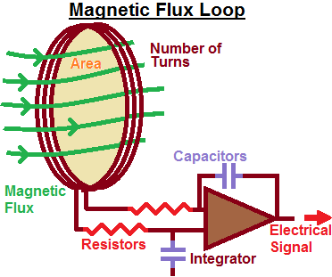
Magnetic flux loop. WikiHelper2134 at en.wikipedia, CC BY-SA 3.0
FLUX DENSITY DUE TO A LONG STRAIGHT WIRE
Imagine a ring of flux of cross-sectional area A, around the wire at a distance r from the wire. The wire can be considercd as part of a very large single-turn coil, that is, N = 1. Therefore current:
I = Φl / μ0A
The length l of the ring of flux is 2πr and, since Φ = BA:
I = BA 2πr / μ0A
Rearranging, we get:
B = μ0I / 2πr
EXAMPLE
Calculate the magnetic flux density around a straight wire carrying a current of 10 A at a distance of (a) 10 cm, (b) 20 cm, (c) 100 cm. (The permeability of free space μ0 = 4π × 10-7 NA-2.)
To solve this question (a), we use the equation for magnetic flux density:
B = μ0I / 2πr
= 4π × 10-7 × 5 / 2π × 10 T
Magnetic flux density at 10 cm = 2 × 10⁻⁵ T
(b) Since r is inversely proportional to B, and since r doubles here, B will halve to 1 × 10⁻⁵ T.
(c) With a value for r of 100 cm, the field strength is 2 × 10⁻⁶ T
THE EFFECT OF IRON
Iron has a very large relative permeability, which is why it is useful for making electromagnets, for example. When a coil is wound on a soft iron core, the magnetic field produced is about a thousand times stronger than it would be if the iron were not there. Iron also has the property of losing most of the magnetism as soon as the current stops flowing. This is why it is described ‘soft’. A magnetically ‘hard’ metal such as steel would retain much of the magnetism if it were used in the same coil. The magnetic flux density in a solenoid with an iron core is:
B = μrμ0 NI / l
Where N number of turns and l = length of flux loop. The value of μr for iron is about 1000.
We can say that iron is a ‘good conductor’ of magnetism. Many other magnetic materials have high relative permeabilities but are less dense than iron. These find uses where light weight is an advantage, such as in miniature earphones and the small motors used inside CD and DVD drives.
MAGNETIC CIRCUITS AND SOME ELECTROMAGNETIC DEVICES
Many simple electromagnetic devices can be understood by using the idea of magnetic circuits. One is the electromagnetic relay, which allows remote switching of several circuits at once. If we examine the flux path in a relay, we see that there is a ‘high reluctance’ air gap between the core of the electromagnet and the armature. The flux in this magnetic circuit is weak. When the electromagnet is ‘energized’ by a current in it, the armature is attracted towards the electromagnet core. This reduces the reluctance of the magnetic circuit and a strong flux is established. It should also be noted that the force between the core and the armature is in a straight line and that the armature moves in the same direction.
Many simple motors also produce rotation when the rotor moves to make a magnetic circuit with a lower reluctance. They are called reluctance motors and are used in disk drives and fans in computers. The stepper motor found in all computer printers is also a more sophisticated relative of the reluctance motor.
The figure below shows a simple reluctance motor. The rotor can be a permanent magnet or an electromagnet (or even a soft iron bar).
When the coils are energized so that one pole becomes a north pole and the other a south pole, the rotor experiences a sideways alignment force. In trying to line up, the rotor is reducing the ‘high reluctance’ gap in a magnetic circuit so that a stronger flux path can be established. The coils could be connected to an a.c. source. As the rotor turns it is in turn attracted to and repelled from the changing poles, continually trying to produce the lowest reluctance path for the flux. (The rotational speed of this motor will depend on the frequency of the a.c. supply. These are often also called synchronous motors.)
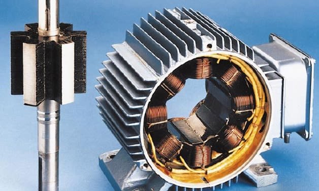
The reluctance motor. Hamidreza D - Own work, CC BY-SA 4.0
FORCES ON WIRES CARRYING CURRENTS
In a wire carrying a current and placed at right angles to a magnetic field. We can predict the direction of the force on the wire by using Fleming’s left-hand rule. The wire will tend to move in the direction of the force. This link between a wire carrying a current and its movement in a magnetic field is used in the moving coil electric motor.
The size of the force F depends upon the current I in the wire of length l in the magnetic field of strength B. That is:
- F α I, the current in the wire
- F α l, the length of wire in the field
- F α B, the magnetic flux density
Taken together, these can be expressed as:
F = kIlB
where k is a constant.
We choose the units of B to make k = 1, as follows. Suppose the magnetic field is such that a wire 1 metre long carrying a current of 1 ampere feels a force of 1 newton. We shall define the flux density B as 1 newton per ampere metre (N A-1 m-1). Therefore we have:
1 N = k × (N A-1 m-1) × 1 A × 1 m
The newton per ampere metre is called a tesla, symbol T. Small magnetic fields are measured in μT (micro-tesla). The magnitude of the Earth’s magnetic field varies between 24 μT and 66 μT. In the UK it is about 49 μT. Under these conditions k = 1. So we have:
F = IlB
By writing the equation for the force like this we are being consistent with other ‘forces in fields’:
- In a uniform electric field, force = charge × electric field strength (F = q × E)
- In a gravitational field, force = mass × gravitational field strength (F = m × g)
The general idea being:
Force = magnitude of quantity feeling the force × field strength
The ‘thing’ feeling the force in a magnetic field is a current-carrying wire (Il). So:
Magnetic force = Il × B
The force on a coil of N turns would be N times greater than on a single wire, namely N × IlB.
Force F is a maximum when the field and current are perpendicular (with magnetic field constant). If the angle is smaller, the force is reduced.
F = Il × B sin θ
A special apparatus for measuring the magnetic flux density is known as the current balance.
EXAMPLE
Calculate the flux density of the magnetic field that will apply a force of 0.1 N per metre to a wire carrying a current of 7 A.
Solution: Since F = IlB or B = F / Il, then B = 0.1 N / 7 A × 1 m = 0.0143 N (Am)‑1
Flux density = 14.3 mT
I guess I should be stopping here for now. But, in my next article, I will continue by discussing on how the unit of electric current, the ampere was being determined and also on forces on charged particles in beams with some other interesting aspects of electromagnetism.
Till then, I remain my humble self, @emperorhassy.
Thanks for reading.
REFERENCES
https://en.wikipedia.org/wiki/Electromagnetism
https://phys.org/news/2017-10-electromagnetism-everyday-life.html
https://en.wikipedia.org/wiki/Magnetic_flux
https://circuitglobe.com/what-is-a-magnetic-circuit.html
https://www.sciencedirect.com/topics/engineering/magnetic-circuits
https://en.wikipedia.org/wiki/Magnetic_circuit
https://dipslab.com/difference-between-electrical-circuit-and-magnetic-circuit/
https://circuitglobe.com/difference-between-magnetic-and-electric-circuit.html
https://www.saburchill.com/physics/chapters/0050.html
https://www.allaboutcircuits.com/video-lectures/magnetism-and-electromagnetism/
https://www.britannica.com/science/magnetic-circuit
https://www.electronics-tutorials.ws/electromagnetism/magnetism.html
https://science.howstuffworks.com/electromagnet.htm
https://www.eolss.net/Sample-Chapters/C05/E6-39A-01-02.pdf
http://physicstasks.eu/2112/magnetic-force-between-two-wires-carrying-current
Congratulations @emperorhassy! You have completed the following achievement on the Steem blockchain and have been rewarded with new badge(s) :
You can view your badges on your Steem Board and compare to others on the Steem Ranking
If you no longer want to receive notifications, reply to this comment with the word
STOPTo support your work, I also upvoted your post!
Very nice readable discussion of a very complex topic! I personally like the equations as this can serve as a nice reference for those rare times I’m investigating an issue, or more commonly, curious about something I read :)
Thanks for your nice comment, @jdkennedy.
This post has been voted on by the SteemSTEM curation team and voting trail. It is elligible for support from @curie and @minnowbooster.
If you appreciate the work we are doing, then consider supporting our witness @stem.witness. Additional witness support to the curie witness would be appreciated as well.
For additional information please join us on the SteemSTEM discord and to get to know the rest of the community!
Thanks for having used the steemstem.io app and included @steemstem in the list of beneficiaries of this post. This granted you a stronger support from SteemSTEM.
The physics and much of the technological advances that we have today, are largely due to electromagnetism and what Nikolas Tesla began to do, after these discoveries the door was opened for many new creations and the advancement of technology
You are absolutely right, @carloserp-2000. Thanks for coming around.
Just one little thing:
Actually, it does only accelerate the, to 6.5 TeV today. And it was 3.5 TeV back in 2008 :).
Thanks for the information, @lemouth.