NEWTON ON THE MOVE: Going Around The Bend
In the design of high-speed trains (HSTs), fuel costs are minimized by reducing friction: friction with the air is kept low, while friction with the track is set at a sufficiently high level for safety. The photograph is of the front of a high-speed train. The train is shaped like this to reduce the frictional force (drag) caused by moving through a fluid (air). The resulting low ‘drag coefficient’ reduces the energy loss at high speed and so increases the train’s maximum speed. The rear of the train, too, needs to be the right shape, to minimize air turbulence, which also wastes energy.
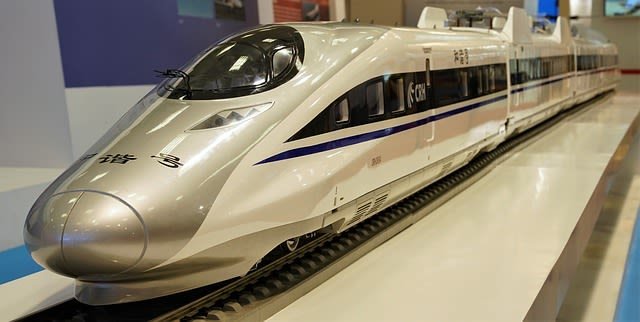
Chinese High-Speed Train. Pixabay
The mass of the train depends on the number of passengers, so the applied forces needed to accelerate and brake have to adjust to this. In emergencies, deceleration may have to be quite rapid but still safe, so great care is taken in designing the braking systems. The geography of the track is important: a longer route may save energy if it avoids inefficient changes between kinetic and potential energy, such as when a loaded train goes up and downhills.
A modern vehicle with low drag travelling at high speed experiences the same kind of force that allows aircraft to fly – aerodynamic lift. Trains and cars are unlikely to take off – but the effect is to reduce the ‘supporting’ force between the ground and the vehicle’s wheels. There must be this supporting force to produce the frictional forces that a train needs in order to accelerate or decelerate. If friction is reduced too much, traction is lost and the driving wheels will simply skid.
When a train travels round bends at speed it needs a centripetal force to keep it moving in the arc of the circle. This is provided by the contact force of the track against the wheels. It would be better if the centripetal force acted through the centre of mass of the train, which is higher than the track contact. As it doesn’t, there is a tendency for the train to topple over as a result of the turning effect of the weight and the contact force acting at a lower point. The faster the train, the worse the effect – the centripetal force varies as the square of the speed. It helps stability if the centre of mass is low, and this is a major feature for all HSTs. In the French TGV the centre of mass is so low that even when it is derailed the chance of the compartments turning over is very small. No modern trains have ever fallen sideways because they round a bend too quickly.
It also helps if the track is tilted (banked) at the bend so that the centripetal force acts closer to the centre of mass, reducing the turning effect. But if the track is also to be used for slower trains, passengers will tend to slide ‘downhill’ and start to get worried. It is equally worrying for passengers when HSTs go around a tilted track at high speed – they are forced ‘uphill’ to the outside of the bend. Also, their drinks and plates slide off the table.
Actually they don’t – they are just stubbornly obeying Newton’s first law of motion, carrying on in a straight line while the table slides away beneath them!
The current solution to passenger comfort is to use tilting trains. The carriage is made to swing as sensors detect that the track is tilting and an accelerometer measures the inward acceleration. This data is used by a computer to tilt the carriage just enough to keep passengers and coffee cups stable. It works because the contact force between cup and table (and passenger and seat) has a component towards the centre of the curve and so provides, with the help of friction, enough force to keep things stable.
Tilting trains have been in use in Italy, Spain and Scandinavia for several years. In Britain, Virgin Rail has upgraded the West Coast line between London and Glasgow to take tilting trains with a maximum speed of 225 km/h (140 mph).
The ideas in this article…..
Newton’s laws of motion are particularly important for an understanding of the topic of transport – and for mechanical engineering in general. The modern world relies on an ability to move materials and people quickly, efficiently and safely from place to place. We shall apply fundamental ideas about mass, force, velocity, acceleration, momentum, impulse and energy not only to the motion of vehicles. We shall also look at the behaviour of fluids (liquids and gases) to understand how ships float and aeroplanes fly. Transport systems have to take account of the fact that vehicles move through a fluid (usually air) and that the fluid is an important restraint on motion.
But a moving fluid carries kinetic energy and so can be used to do work. Moving water is used to drive turbines in hydroelectric power stations. The energy of moving air is used in wind turbines, a cheap source of energy but with an impact on the visual environment which can be controversial.
CONSERVATION OF MOMENTUM AND ENERGY IN TRANSPORT SYSTEMS
This chapter will deal with the key ideas of momentum and energy in relation to moving objects. Both total energy and momentum are conserved when engines are used to move vehicles such as cars, trains and rockets – but kinetic energy is not conserved.
Think about a rocket: the exhaust gases and the rocket itself gain kinetic energy from burning fuel, but a significant fraction of the energy in the fuel mixture is transferred to the random motion of gas particles and does not appear as useful kinetic energy of the rocket vehicle itself. The same applies to road and rail transport vehicles, which gain their energy from burning fuels. Even electric traction engines ultimately depend on the fuels used in power stations to generate electricity.
Not all the energy transferred by a transport system appears as kinetic energy. Some energy is usually transferred to or gained from gravitational potential energy, for example when aircraft climb and land, and ground vehicles go up and downhills. But what goes up must come down and there is no net change in gravitational potential energy for a vehicle that always returns to its starting level. There are usually some friction losses: for example, energy is lost to the surroundings when vehicles brake (the brake discs get hotter).
Nevertheless, in all these changes both total energy and momentum are conserved although it is more difficult to keep track of the energy transfers than the momentum changes.
TRACTION AND BRAKING
The control of a car – in accelerating, turning and braking – relies on its contact with the road surface. The key factor is friction between the tyres and the road surface. The area of contact is quite small as is shown in the diagram below.
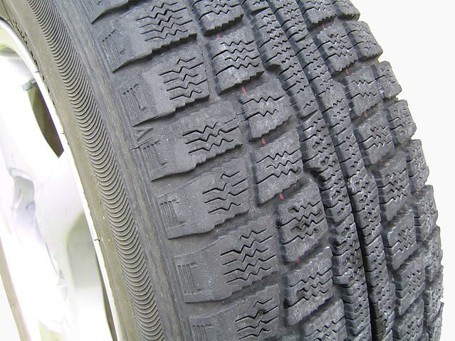
Patterned surface of a tyre showing the area in contact with the ground. Lombroso, Public Domain
EXAMPLE
The mass of a given car is 1000 kg. Its tyre pressure is rated as 2.4 × 10⁵ Pa above normal atmospheric pressure: that is, about 3.4 × 10⁵ Pa. What area of the tyre is in contact with the ground?
Using the definition, pressure = force / area, we get:
Area of contact = weight of car / Tyre pressure = 1000 x 9.8 N / 3.4 × 10⁵ N m-2 = 0.029 m2
This is a total area of 290 cm2. Thus the area of contact per tyre is 72 cm2 – roughly the area of the palm of your hand.
As the car wheel turns, the part of the tyre in contact with the ground is instantaneously at rest with reference to the ground. If the car is accelerating or braking, the force that ultimately acts on the car as a whole must be due to the friction between the tyres and the ground. If there were zero friction the wheels would spin freely and the car would skid out of control – as tends to happen on icy roads. In a figure showing the forces acting on an accelerating car. The maximum value of the frictional force F is decided by the nature of the two surfaces in contact and the normal force N between them. Here the word ‘normal’ has the special mathematical meaning of ‘at right angles to the surfaces at the point of contact’. This force is often called the normal reaction. The relationship is simple:
F = μN
Where μ is a dimensionless number called the coefficient of friction. Its value depends on the nature of the surfaces, and μ is usually lower for surfaces sliding against each other than it is for the same surfaces when they are at rest relative to each other. We, therefore, distinguish between the coefficient of static friction between two particular surfaces and their coefficient of sliding friction. For rubber against a paved road, the static coefficient varies between 0.7 and 0.9. The coefficient for sliding friction is between 0.5 and 0.8; on a wet road, this reduces to between 0.25 and 0.7.
Sliding down a slope
The figure below shows the forces acting on an object that is sliding steadily down a slope. It is not accelerating, so the component of the object’s weight down the slope must equal the frictional force acting up the slope.
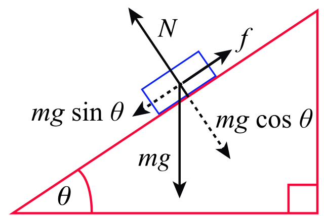
A body on an inclined plane. Jer S, CC BY-SA 4.0
The frictional force is μN where N is the supporting force between the object and the surface of the slope. Thus:
mg sin θ = μN
But N is also due to the weight of the object. In fact, N = mg cos θ, so we can write:
mg sin θ = μmg cos θ
which simplifies to:
μ = sin θ / cos θ = tan θ
This relationship can be used as a simple way of measuring the coefficient of friction between two surfaces. Note that the frictional force F does not depend on the area of the surfaces in contact.
FRICTION AND ACCELERATION
Over-keen drivers ‘burn rubber’ at traffic lights when they try to accelerate with forces greater than can be provided by static friction between tyres and road. The tyre moves relative to the road surface and work done against sliding friction produces local heating. Similarly you may see skid marks when vehicles brake so strongly that wheels ‘lock’, so that again there is relative movement between road and tyre as the tyres slide along the ground. A car may skid if it is made to turn too sharply, that is, in too small a circle. A central force is needed to make a car move in a circle, and again this must be provided by the force of friction between car and ground. Look back to the start of this post to see why a turning vehicle might topple over.
EXAMPLE
A typical value for the coefficient of static friction between a particular tyre and a road is 0.7. Estimate the maximum acceleration that a car of mass 1000 kg can have.
ANSWER
Maximum frictional force F = μN = 0.7 × 1000 × 9.8 = 6.8 kN
The acceleration produced by this force is:
a = F / m = 6.8 × 10³ / 1000 = 6.8 ms-2
But this is a very rough estimate – the two drive wheels share the weight of the car with the other pair of wheels, so the normal reaction N is less than the weight of the car. This means that the maximum possible acceleration is less than that calculated. Motor engineers still find the simple formula F = μW useful, however, where W is now the load on the driving axle, which may be measured (with difficulty at speed) or calculated from theory.
ROTATION: WHEELS AND ROTATIONAL INERTIA
A spinning wheel has both kinetic energy and momentum due to its rotation – even when the wheel is not moving forward. A turning force (or torque) is needed to get a wheel to rotate, and the force does work that appears as kinetic energy. Torque is measured, like the moment of a force, in newton metres (N m). Tests show that it is harder to spin a wheel of large diameter than a wheel of smaller diameter even when both wheels have the same mass. Just as we call the resistance of a mass to being accelerated its inertia (m), so we can also define the resistance of a wheel to being rotated by a turning force as rotational inertia I (also called moment of inertia). The units of rotational inertia are of mass × (distance)2, that is kg m2.
Rate of spin is measured by the angle through which a radius line turns per second, that is, its angular velocity ω. Angular velocity is measured in radians per second. Just as velocity is a vector, so is angular velocity. With α as angular acceleration, comparing linear and rotational motion:
Force = mass × acceleration
F = ma
torque = rotational inertia × angular acceleration
T = Iα
EXAMPLE
A torque of 20 Nm acts on a wheel that is initially still and has rotational inertia of 600 kg m2.
a) What is the angular acceleration produced?
b) At what angular velocity is the wheel spinning after 2 minutes?
c) The wheel is 30 cm in radius. How fast (in ms-1) is a point on the rim moving at this time?
ANSWER
a. Angular acceleration = torque / rotational inertia:
α = 20/600 = 0.033 rad s-2
b. Angular velocity = angular acceleration × time
= 0.033 × 120 = 4 rad s-1
Since by the definition of a radian: distance covered per second by a point on the rim
= angle turned through per second × radius
So the speed of a point on the rim is 4 × 0.30 = 1.2 ms-1
ANGULAR MOMENTUM
Just as linear momentum is defined as mass × velocity, so we define angular momentumn as:
Angular momentum = Rotational inertia x angular velocity = Iω
As with linear motion, Newton’s second law applies:
Linear force = Rate of change of momentum
F = Δ (mv) / Δt = Δp / Δt
rotational torque = rate of change of angular momentum
T = Δ (Iω) / Δt
ROTATIONAL INERTIA OF EVERYDAY OBJECTS
The structure of a wheel may be simplified as shown in the figure below. The spokes are assumed to have negligible mass compared with the rim. All the mass (m) is then at the same distance r from the centre of rotation and the rotational inertia is simply mr2.

In many cases, however, the mass of a spinning wheel is not evenly distributed on the rim. The rotational inertia can be calculated if the distribution is fairly simple, but may in practice have to be measured experimentally. The value of the rotational inertia of a car wheel is quite difficult to calculate mathematically, for example. As a general rule the mathematics involves adding up the contributions of all the small masses, taking into account the square of their distance from the centre of rotation:
I = Σ mr2
Note that the value of rotational inertias of some simple shapes also depends on how the object is spun round an axis.
ROTATIONAL ENERGY
The kinetic energy of a rotating body is ½Iω2. This is the equivalent of the linear formula ½mv2. If the wheel has mass m and is also rolling forwards with speed v it will also have translational kinetic energy ½mv2. The total kinetic energy Ek of a rolling wheel is therefore:
Ek= ½Iω2 + ½mv2
Large vehicles (like some electric locomotives) can reduce the waste of energy in braking by storing linear kinetic energy as rotational energy in massive rotating wheels (flywheels). Track wheels are linked through a gearing system to the flywheel instead of to the usual friction brakes. As the track wheels slow down, the flywheel speeds up, and vice versa.
CONSERVATION OF ANGULAR MOMENTUM
Hold the axis of a bicycle wheel in your hands and get someone to spin it in the vertical plane. Then try to tip the wheel through a small angle away from the vertical. You will experience a mysterious force that seems to oppose the change in direction of the axis. In fact, this is a consequence of the conservation of angular momentum – and Newton’s third law of motion. Newton’s third law states that, when two bodies interact, the force exerted by one body (here, the holder tipping the wheel) brings about an equal and opposite force exerted by the other body (the wheel). So, changing the direction of the axis of spin means altering the angular momentum, not in size but in direction. This requires a force, and as forces occur in pairs there is an equal and opposite force exerted on you as the wheel changes direction. This ‘resistance’ of a spinning wheel to changing its direction of action is what makes a bicycle so stable – as long as the wheels are spinning! Conservation of angular momentum is also of importance to the origin and nature of the Solar System.
REFERENCES
https://www.explainthatstuff.com/motion.html
https://onlinelibrary.wiley.com/doi/abs/10.1002/pssa.2211450215
https://en.wikipedia.org/wiki/Momentum
https://en.wikipedia.org/wiki/Transport_phenomena
Traction and braking control system
https://en.wikipedia.org/wiki/Traction_control_system
http://dynref.engr.illinois.edu/ava.html
https://physics.info/friction/practice.shtml
https://sciencing.com/calculate-acceleration-friction-6245754.html
http://hpwizard.com/rotational-inertia.html
https://opentextbc.ca/physicstestbook2/chapter/dynamics-of-rotational-motion-rotational-inertia/
http://homepage.physics.uiowa.edu/~rmerlino/6Spring11/29006_L11.pdf
https://en.wikipedia.org/wiki/List_of_moments_of_inertia
https://www.livephysics.com/physical-constants/mechanics-pc/moment-inertia-uniform-objects/
https://www.thoughtco.com/moment-of-inertia-2699260
Moment of Inertia and Rotational Kinetic Energy
https://courses.lumenlearning.com/boundless-physics/chapter/rotational-kinetic-energy/