IMAGING IN PHYSICS
Optical lenses, such as the lenses in a camera viewfinder, a telescope or a microscope, allow us to see the images of a wide range of objects. In these instruments, a lens (or several lenses) takes the image to the eye, which has a lens, too. But an image can be formed by many lenses packed side by side in a layer. The eyes of insects have this arrangement, with hundreds of small rod-shaped lenses, each directing part of the image to the creature’s brain.
A photocopier has a similar imaging system. Up to several million cylindrical ‘microlenses’, each only a few micrometres across, form a flat array which scans the item being copied a line at a time. The light from particular points on the copied item passes through the microlenses, and on to the detector, to build up a complete image. The refractive index of the microlenses is graded, which means the microlenses don’t have to be ‘lens-shaped’.
Microlenses are also used in producing the image on the liquid crystal display (LCD) screen of a portable laptop computer. The brightness and clarity of the image are steadily being improved and, at the same time, the energy required to power the equipment is being reduced.
The ideas in this chapter
In today’s world, images have become as important as writing – or even speech – as a means of communicating ideas. Images are rich in information: we say that ‘a picture says more than a thousand words’. The figure below shows some symbols that clearly convey ideas more rapidly and simply than words.
Every day we experience the communicating power of images, particularly through television and advertising. Also, current physics and technology convert complex data into images – from particle tracks in accelerator detectors to ozone concentrations measured by satellites. In this chapter, we will be looking at the basic science and the techniques used to produce images.
First, the chapter deals with the working of a simple thin lens, and how lenses work in imaging devices such as the human eye, cameras, telescopes and microscopes. Images are also produced by mirrors, both flat and curved. The chapter goes on to show how images are displayed and recorded. Finally, I will look briefly at some modern methods of imaging which rely on advances in physics and involve complex technology.
HOW A CONVERGING LENS FORMS AN IMAGE
We are familiar with convex glass lenses. They have equal surfaces that we think of as parts of a sphere, and are called spherical (or simple) lenses. A lens which alters a plane wavefront to make the light waves pass through a point, or focus, is called a converging or positive lens. The wavelengths of the light are shorter after they pass across the air-glass boundary. This is because the speed of the waves is less in glass than in air, and the waves don’t go as far in each period of the wave motion. This drop-in speed causes refraction, meaning that the light changes direction wherever the wavefront is not parallel to the boundary.
Wave diagrams like above are hard to draw, and they also hide some of the features of the light paths. Here, it makes sense to revert to an old but very useful model of light which assumes that light travels in straight lines. The figure shows just some of the light rays. The rays show the direction of the waves, which means that the rays are at right angles to the wavefront. When a ray hits the glass surface, it is refracted as shown. Notice that the light ray hitting the centre of the lens does so at 90° and that light rays increasingly far from the centre of the lens hit the surface at smaller and smaller angles. I will return to this soon.
Look at the figure below, which shows light passing through a plane surface, such as the surface of a glass block. The line at right angles to the boundary is the normal, and we can see that the angle i made with the normal by the incident ray is greater than the angle r of the refracted ray. At the same time, as i increases, so r increases, while remaining less than i. This shows that the light rays are obeying Snell’s law, the law of refraction:
sine of angle of incidence/sine of angle of refraction = sin i/sin r = constant, n
The constant n is the refractive index (air to glass for glass lenses). Looking at the figure in close-up, it shows rays from a point source passing through a lens. The radius lines of the curved surface are shown extended beyond the surface as normal lines. We can see again that the law of refraction applies to the rays as they cross the air-glass boundary.
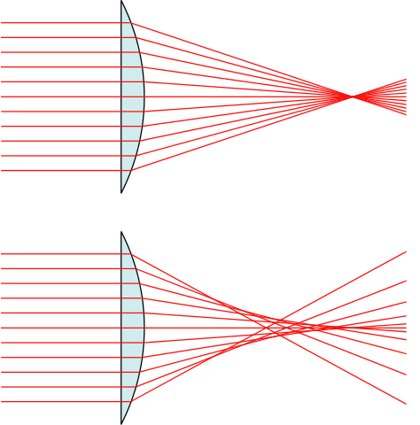
The spherical geometry of the simple lens makes the rays converge (but not accurately) to one point or focus. For parallel rays (that form a plane wavefront), is called the principal focus. The distance of this point from the centre of the lens is called the focal length of the lens. A lens has two principal focuses (or foci), one on each side of the lens, at equal distances from it.
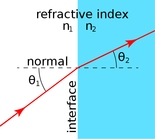
Refraction of a light ray. Ulflund , CC0
In practice, the focus for simple spherical lenses is only at a point if the diameter of the lens is very small compared with the radius of curvature of its surfaces. Otherwise, the lens forms a partly blurred image. A lens defect like this, caused either by the shape or the material of the lens, is called an aberration. For a lens with spherical geometry, it is called spherical aberration. Removing aberrations is technically difficult, which explains why good optical instruments, such as camera lenses, are expensive.
PREDICTING THE IMAGE
From a diagram showing how a simple lens forms an image of an object, the position and size of an image either by drawing or by using formulae can be predicted.
Drawing to find the image
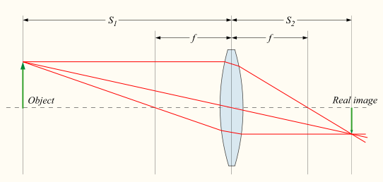
We can draw any number of rays to help us find the position and size of an image, but the three rays that are most helpful to draw are shown, with the usual labels we use when drawing ray diagrams. In an upright object OX close to a lens. The object could be anything, but by convention it is drawn simply as an arrow. Any ray that is parallel to the principal axis of the lens is refracted to pass through the principal focus, F. In this way, we can predict the direction of the ray. Note that in ray diagrams such as this, the rays are assumed to change direction at a line that represents a plane in the centre of the lens.
We use the same idea for ray 2. Going through F’, it emerges from the lens parallel to the principal axis. The third useful line, for ray 3, goes straight through the centre of the lens – it does not deviate. (But at the centre of the lens, the faces are parallel to each other. If the lens is thin compared with the distances of object and image, which we assume, the slight sideways displacement of the ray is not significant.)
A camera lens forms a real image of a distant object. w:en:DrBob - w:en:File:Lens3.svg, GFDL
All three rays pass through the same point, Y. They all started at X, and it is clear that a screen placed at Y would catch them all together again: Y is a focused line of X. Similarly, any point on OX would give a focused image of itself somewhere between I and Y. IY is a real image. A real image is one that can be caught on a screen: surprisingly some images can’t and are called virtual images. These construction rays can be drawn to scale to find the position and relative size of the image of any object placed in front of the lens. Objects viewed through a lens, and their images, are usually much smaller than the distances they are from the lens. In such cases, it is best to make the vertical scale larger than the horizontal one
Finding the image by formula
It is usually quicker and more accurate to find the position and size of an image by using the lens formula:
1/u + 1/v = 1/f
Where u is the distance of the object from the lens centre, i.e the object distance. v is the distance of the image from the lens centre, the image distance, and f is the focal length of the lens. To find the size of the image we can use the equation
Image size = object size × V/U.
You can now find the position and size of any image simply by inserting the other given values in the formula.
THE IMAGE IN A DIVERGING LENS
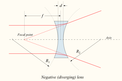
The figure below shows a lens with concave spherical surfaces and what happens to parallel light rays (that is, a plane wavefront coming from a distant object) when they pass through it. The rays are refracted so that they seem to diverge from a single point, F. This point is the principal focus of a diverging lens. As light doesn’t actually come from the point, or pass through it, it is a virtual focus.
The figure shows how a diverging lens forms an image of an object. As for a converging lens, you would see the image by looking at the object through the lens. But light doesn’t actually pass back through the diverging lens to the image so you cannot catch the image on a screen. It is, therefore, a virtual image.
Diverging lens. DrBob, CC BY-SA 3.0
The sign convention
The lens formula works for all simple optical devices (even mirrors). But we have to know whether the images, principal lenses – and even objects – are real or virtual. Where they are virtual, the convention is to give negative values to distances measured from them to the lens or mirror. For example, the principal focus of a diverging lens is virtual, so its focal length is given a negative sign.
Suppose I place a real object 20 cm from the diverging lens. The principal focus of the lens is 10 cm from the lens, so its focal length is -10 cm. The lens formula gives:
1/20 + 1/v = -1/10
So: 1/v = -1/10 – 1/20 = -3/20
And: v = -20/3 = - 6.7 cm
So the distance of the image from the lens centre is 6.7 cm, and the negative sign tells us that the image is also virtual.
THE POWER OF A LENS AND ITS IMAGE QUALITY
In optics, lenses are usually described in terms of their power. The more powerful the lens, the closer to the lens is the image that the lens forms of a distant object. The power of a lens is defined as the reciprocal of its focal length f measured in metres:
Power = 1/f
The unit of power is called the dioptre, symbol D, and so a lens of focal length +10 cm (0.1 m) has a power of +10 D. A diverging lens of focal length -5 cm (-0.05 m) has a power of -20 D. This way of describing lenses lets us work out what happens when two lenses are used together. The combined power of the lenses is simply the sum of the powers of each lens, bearing in mind their signs.
THE CAMERA LENS AS AN EXPENSIVE HOLE
We have seen that the quality of the image made by a lens depends on its shape. Image quality also depends on the aperture of the lens, that is, the part of the lens through which light is allowed to pass. (Though the lens diameter is fixed, the aperture can be varied.)
A lens of large diameter captures more light and produces a brighter image than a smaller diameter lens. However, it is difficult and expensive to correct for aberrations in large aperture lenses. So, for example, in ordinary cameras with a single lens, the lens is usually ‘stopped down’ to make the picture sharper. The light used to form the image passes through the central region only of the lens, and this reduces spherical aberration.
The quality of the image is also affected by diffraction. The image is blurred as points on the object become circular diffraction patterns. Points on the image subtending an angle smaller than a certain value of θ are not seen as separate; their resolution is not possible. θ is determined by wavelength λ and aperture, d in the Rayleigh criterion:
θ = λ/d
Diffraction effects are reduced when the aperture is large, so accurate optical instruments have a design conflict. Large aperture means better resolution, as the Rayleigh criterion tells us, but more spherical aberration. Small aperture reduces aberration but worsens resolution.
I will like to stop here for now. In my next post, I will discuss on mirrors and some optical instruments with two components.
REFERENCES
https://www.ldoceonline.com/Physics-topic/imaging
https://phy.duke.edu/research/research-areas/imaging-medical-physics
https://www.physicsclassroom.com/class/refrn/Lesson-5/Converging-Lenses-Ray-Diagrams
https://www.britannica.com/technology/spherical-aberration
https://en.wikipedia.org/wiki/Spherical_aberration
https://www.effinghamschools.com/cms/lib4/ga01000314/centricity/domain/702/599-603.pdf
https://www.azooptics.com/Article.aspx?ArticleID=675
https://courses.lumenlearning.com/physics/chapter/25-6-image-formation-by-lenses/
https://www.physicsclassroom.com/class/refrn/Lesson-5/Diverging-Lenses-Object-Image-Relations
https://www.explainthatstuff.com/lenses.html
https://www.photoreview.com.au/tips/lens-tips/lens-quality-and-image-sharpness/
https://www.quora.com/How-do-different-lenses-affect-the-photo-quality
@tipu curate
Upvoted 👌 (Mana: 25/30 - need recharge?)
This post has been voted on by the SteemSTEM curation team and voting trail. It is elligible for support from @curie and @minnowbooster.
If you appreciate the work we are doing, then consider supporting our witness @stem.witness. Additional witness support to the curie witness would be appreciated as well.
For additional information please join us on the SteemSTEM discord and to get to know the rest of the community!
Thanks for having used the steemstem.io app and included @steemstem in the list of beneficiaries of this post. This granted you a stronger support from SteemSTEM.