APPLICATIONS OF ELECTROMAGNETIC INDUCTION: Eddy Currents, The Dynamo, and the Behaviour of a Simple D.C Motor.
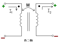
The flux in the core of a transformer induces
currents in the coils at right angles to it. Why doesn’t the flux induce currents
in the core itself? After all, the core is made from iron or some similar
magnetic material, which is also a good conductor.
The answer is it does, and if the core were solid the currents induced would make the core very hot and the energy transferred to the secondary coil would be far less. Currents induced in conductors like this are called eddy currents. The term ‘eddy currents’ came about because the charge moves in a swirling pattern, rather like the eddy currents we see in river water.
Eddy currents can be useful. The figure below shows a simple demonstration of eddy currents. The pendulum has an aluminium vane. When it swings between the poles of a magnet its motion is very heavily damped – it slows down and stops after a few swings.
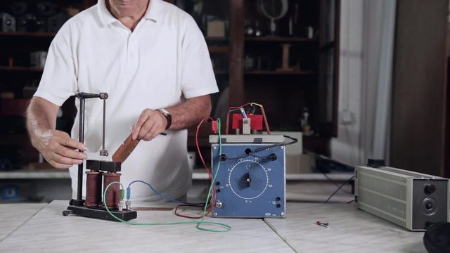
This effect, sometimes called ‘magnetic braking’, is due to the currents induced in the aluminium as it cuts through the magnetic field. The currents flow in loops within the aluminium and, like all induced currents, they obey Lenz’s law. That is, they flow in the direction that opposes the change that causes them.
As the vane enters the field (and B is getting stronger), an eddy current is induced in the vane. The moving electrons in the eddy current experience a force in the field of the magnet that opposes the motion of the vane, so slowing the vane. The force on the moving electrons is the same as the ‘motor effect’.
When the vane moves out of the field (and B is now getting weaker) the direction of the induced current reverses, and so does the motor effect’ force. This slows the vane down more. After a few swings, it comes to rest.
If the solid vane is replaced by one with slots cut into it, the oscillating vane is affected far less and continues to swing for longer. The slots restrict the possible paths for eddy currents and effectively reduce the size of any currents induced.
Magnetic braking can be useful where damping is required, But eddy currents are a nuisance in many practical situations, because they dissipate energy due to electrical resistance of the material. This dissipation of energy can itself sometimes be useful, for example in induction heating, but in transformers and motors the heating is not only wasteful but potentially dangerous.
In practice, transformers are very efficient devices. Very little energy is lost in heating the core because eddy currents are reduced by careful design. The core in low-frequency transformers is not made from a solid block of material but it is laminated. That means it is made up of many thin, lacquer-coated slices of the material, each insulated from its neighbour, which are bound together to make a high permeance (or low reluctance) core. The electrical resistance at right angles to the flux is very high so eddy currents are very small. Remember that permeance is a measure of how well a material allows a flux to be set up in it while reluctance is the reciprocal of permeance.
Modern ferrite materials are made from a paste of small iron oxide particles baked into a solid shape. The particles are close enough to produce good magnetic properties (high μr) but eddy currents are reduced to a minimum.
THE DYNAMO
We have seen that the large-scale production of electrical energy has developed from Faraday’s experiments. Power stations all over the world, whether burning fossil fuels or using wind power, produce induced currents. In the UK, electricity is generated as an alternating current. The equation for an alternating current is:
I = I0 sin 2πft
Where I0 is the peak current. The simple bicycle dynamo and the generators used in power stations are basically the same.
Using a simple rectangular loop that is rotating about an axis OP in a uniform magnetic field of flux density B tesla. Because the sides of the loop WX and YZ are moving at right angles to the field but in opposite directions, the e.m.f.s induced in each side will drive a current in the same direction around the loop.
After half a cycle, WX and YZ will have changed places. The current passes out of the loop through slip rings. Each end of the circuit is always in contact with one slip ring, allowing for a continuous current. The current in the galvanometer will now be reversed. After another half-cycle the loop is back where it started and the current will be in the same direction as in the first half-cycle.
During each half-cycle the size of the current rises and falls. Suppose the plane of the loop makes an angle a with the magnetic field and that the sides WX and YZ have a length y and are moving at a speed v. The induced e.m.f. in each side will be given by:
ε = Byv sin(90° – a) = Byv cos a
Now suppose the angular velocity of the loop is ω and it takes t seconds to move through an angle a. Then:
a = ωt
and the velocity v is related to ω and the width of the coil x by:
v = ωx/2
So the total e.m.f. due to both sides is given by:
εtot = 2Byωx/2 × cos ωt = Bxyωcos ωt
But xy = A, the area of the loop, and ω = 2πf, where f is the frequency of rotation. Therefore, for a coil of N turns:
εtot = 2πfNBA cos 2πft
This is the equation of an alternating voltage of peak value:
ε0 = 2πfNBA
So that:
εtot = ε0 = 2πft
BEHAVIOUR OF THE SIMPLE D.C. MOTOR
The current drawn by a simple motor varies in an interesting way. When a motor with no load is switched on, the initial current drawn by the rotor coil from its power supply is very high, but it quickly drops to a much lower value. If the motor is then loaded, the current drawn by the motor gradually increases. Another important fact is that when the motor does work its speed decreases.
The motor rotates because of the force on a wire carrying a current, IlB. Current I is driven by an applied e.m.f. ɛs (from the supply). As the coil rotates, an e.m.f. ɛi is induced in the coil. This e.m.f. tends to drive a current in the opposite direction to the current from the power supply (Lenz’s law). The size of this induced e.m.f. depends on the speed of rotation of the coil. The faster the coil rotates, the larger the induced e.m.f. The resultant current as measured by an ammeter arises from the sum of the two e.m.f.s. The figure below shows a circuit diagram for a simple motor.
When the motor starts from rest there is no induced current. Therefore the initial current measured on the ammeter is high. As the motor’s speed increases, so does the induced e.m.f., and the total current measured on the ammeter drops. If the motor does work and it slows down, the induced e.m.f. decreases and the measured current increases, delivering more energy to the motor.
If we consider the resistance in the rotor circuit (this includes any internal resistance of the power supply), we can say:
total resistance = (e.m.f. of supply - induced e.m.f.) / current
ог:
R = ɛs - ɛi/I
We can rearrange this to give the current:
I = ɛs - ɛi/R
I is the current that is measured by the ammeter.
Assuming the resistance stays constant, which is a reasonable assumption if the coil does not get hot, then we can see that the current depends on the difference between the applied and induced e.m.f.s. The induced e.m.f. ɛi is often referred to as the back e.m.f.
The following equation also helps us understand the energy balance of the motor:
IR = ɛs - ɛi
or:
ɛs = ɛi + IR
Multiplying both sides by the current, I, we get:
ɛsI = ɛiI + I2R
Put in words, this says:
power from supply = useful power + power lost in heating rotor coil
Power lost in heating the rotor coil is also known as ‘copper losses’.
_80_degree_split_ring.gif)
This is a rather simplified picture of a real motor. In order to make the magnetic field as strong as possible, the coil in most motors is wound on a soft iron “former”. This introduces the possibility of some eddy current losses, even though the material will be laminated to minimise them. Another source of energy loss is called flux loss’: the inevitable gap between the rotor and the poles of the magnet (or electromagnet) is a low permeance (or high reluctance) section in the magnetic circuit. This reduces the flux linking them as some of the flux spreads out or ‘escapes’ at the gap.
Instead of permanent magnets, most practical motors use electromagnets, usually called ‘field coils’: several coils are wound on a high permeability former to provide a strong field with the desired shape. Such a motor then has field coils and the rotor coil. These can be connected in parallel (shunt wound) or in series.
INDUCTANCE
In the simple demonstration circuit of the figure below the two bulbs are identical and the resistance of the variable resistor R is the same as the resistance of the coil L. The coil should have a soft iron core for the effect to be noticeable. When the switch is closed, the bulbs both light up but do not come on together. There is a noticeable lag between the time when the bulb in series with the resistor lights up and when the other bulb lights up. When both are lit they have the same brightness. The effect of slowing down the growth of the current is described as the inductive effect of the coil. Hence such coils are also called inductors.
When the circuit is first switched on, charge begins to flow in the inductor. This current creates a magnetic field in the coil where none existed before, that is, there is a changing magnetic field. The changing magnetic field induces a voltage that opposes the change (Lenz’s law). It does this by creating an e.m.f. in the opposite direction to the e.m.f. from the applied voltage. As a result, the current in the coil builds up more slowly than in the simple resistor. However, eventually the current in the coil reaches a maximum. This maximum current is determined by the applied voltage and the total resistance in the circuit.
The final steady current depends on the supply and the resistance of the inductor:
I = applied e.m.f. / total resistance
Although the build-up of current may take only a small fraction of a second can see from the initial gradient of the curve that the rate of change of current (dl/dt) at the start is constant. This rate of change of current depends on two factors: the applied voltage and the inductive effect of the coil. Experiment shows that the initial rate of increase of current is directly proportional to the applied voltage i.e:
V α dI/dt
The constant of proportionality is a property of the coil called the self-inductance of the coil and is given the symbol L:
V = LdI/dt
The unit of self-inductance is volt second per amp (V s A-1) or the henry (H)
EXAMPLE
A 50 mH inductor is connected to a 3 V d.c. supply. By how much does the current increase in the first 10 ms?
ANSWER: We can use the equation: V = LdI/dt
Assuming the rate of change of current is constant in this time interval, the increase in current ΔI is given by
V dt/l = (3 × 10 × 10-3) / 50 × 10-3 = 0.6A
When the switch in the circuit is opened, the inductor current collapses much more quickly. This reducing current induces a large e.m.f. in the opposite sense to the applied e.m.f. We can demonstrate the size of this e.m.f. by connecting a neon bulb across the inductor. A neon bulb requires a voltage of at least 80 V across it for it to light. When the switch in this circuit is opened the bulb will light.
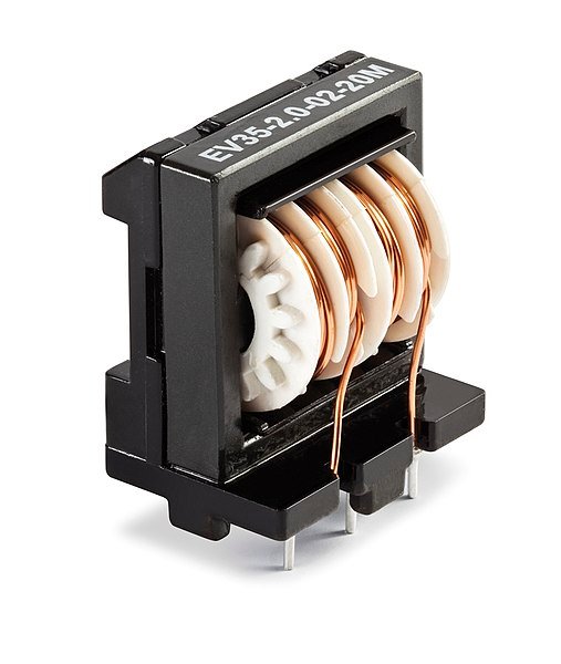
A ferrite core inductor with two 20 mH windings. Holger Urban, CC BY-SA 4.0
Induction coils (The Ignition system for a car)
The motive force of a petrol engine is supplied when a mixture of petrol and air explodes. This explosive mixture is ignited by the spark from a spark plug, and the spark itself is produced when about 2 to 3 kV are applied across the spark gap.
Using induction, this high voltage comes from the 12 V car battery. The rotating cam in the distributor opens the ‘points’, and so cuts off the current in the primary coil. The sudden drop in the primary current means that the strong magnetic field due to that current also suddenly collapses. The rapid change then induces a very high voltage in the secondary coil.
This voltage is applied to one of the spark plugs through the rotor arm. In one cycle of the cam, a high voltage is induced four times and is applied to each of the four plugs in turn.
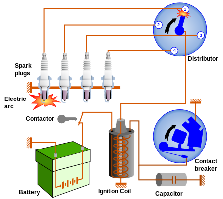
Ignition circuit diagram for mechanically timed ignition. Frédéric MICHEL and PiRK, CC BY-SA 3.0
Current variation in circuits containing inductance
We can treat the inductor as being similar to the motor I have described. Like the motor, the e.m.f. of the supply is opposed by the e.m.f. induced in the inductor. The current in the circuit is given by:
Current = (e.m.f. of supply - e.m.f. of inductor)/total resistance of circuit
or in symbols:
I = (V – LdI/dt)R
which can be rearranged as:
dI/dt = (V-IR)/L
This is a first-order differential equation which can be solved using calculus. The solution to this equation is another equation, which describes the exponential growth of the current.
SUMMARY
By the end of these chapters on APPLICATIONS OF ELECTROMAGNETIC INDUCTION, you should be able to:
- Describe Faraday’s experiments on electromagnetic induction.
- Understand Faraday’s laws of electromagnetic induction, leading to: ε0 = -N(dφ/dt).
- Use the equation V = vlB to calculate the e.m.f. induced in a moving wire.
- Use Lenz’s law to predict the direction of an induced current.
- Describe the behaviour of a simple transformer.
- Describe the behaviour of a simple moving coil dynamo.
- Describe how eddy currents are induced and give examples of their effects.
- Describe the behaviour of a simple d.c. motor under variable loads.
- Describe the self-inductance of a coil, V = L (dI/dt), and the behaviour of inductors in d.c. circuits.
REFERENCES
https://www.toppr.com/guides/physics/electromagnetic-induction/eddy-currents/
https://www.magcraft.com/blog/what-are-eddy-currents
https://en.wikipedia.org/wiki/Eddy_current
https://www.explainthatstuff.com/generators.html
https://www.bbc.co.uk/bitesize/guides/zgb9hv4/revision/1
https://edisontechcenter.org/generators.html
https://en.wikipedia.org/wiki/Dynamo_theory
https://en.wikipedia.org/wiki/Dynamo
https://community.nxp.com/docs/DOC-1067
https://elearnstation.com/scenari/DC%20MACHINES/co/module_DCMACHINES_2.html
https://www.motioncontroltips.com/what-is-linear-behavior-for-dc-motors/
https://en.wikipedia.org/wiki/DC_motor
https://www.britannica.com/science/inductance
http://hyperphysics.phy-astr.gsu.edu/hbase/electric/induct.html
https://www.electrical4u.com/what-is-inductor-and-inductance-theory-of-inductor/
https://www.electronics-tutorials.ws/inductor/inductance.html
https://www.electronics-notes.com/articles/basic_concepts/inductance/inductance-basics-tutorial.php
https://en.wikipedia.org/wiki/Inductance
https://www.britannica.com/technology/ignition-system
https://link.springer.com/content/pdf/10.1007/978-3-658-03972-1_7.pdf
https://www.howacarworks.com/basics/how-the-ignition-system-works
This post has been voted on by the SteemSTEM curation team and voting trail. It is elligible for support from @curie and @minnowbooster.
If you appreciate the work we are doing, then consider supporting our witness @stem.witness. Additional witness support to the curie witness would be appreciated as well.
For additional information please join us on the SteemSTEM discord and to get to know the rest of the community!
Thanks for having used the steemstem.io app and included @steemstem in the list of beneficiaries of this post. This granted you a stronger support from SteemSTEM.