ANALOGUE METHODS OF MODULATION: Radio and Telephone Systems.
So far, in my last post on communication physics, I have concentrated on radio signals. Telephone signals can also be amplitude modulated or frequency modulated. Many telephone signals can be sent down a cable – or today, an optical fibre – in a band like a band of radio signals. I will discuss optical fibres later.
Amplitude modulation and frequency modulation
are analogue methods of modulation. By ‘analogue’ I mean that there is a direct
relationship between the information signal and the electronic signal that is
transmitted. In the case of radio, the loudness and pitch of the sound are used
to change the amplitude and frequency of the transmitted signal. Analogue
signals change continuously, covering a range of possible values. By so doing,
such signals take up a slice of frequency space, occupying a small part of the
electromagnetic spectrum. Both AM and FM signals travel a limited distance, and
beyond this, they are so weak that they are difficult to detect.
LIMITATIONS OF AM AND FM
We have seen that AM and FM are widely used in radio and telephone communication. Some television systems use AM for picture information and FM for the sound. So AM and FM are certainly an effective means of communication. But they cannot provide the flexibility and reliability required for some modern communications.
They are also very open: once a signal is transmitted, anyone with a suitable receiver can listen in. They are both ‘real-time’ systems, which means that the signal can be received only at the time it is transmitted. As radio airwaves become more congested, this is a disadvantage.
Comparison of AM and FM modulated radio waves. Berserkerus, CC BY-SA 2.5.
NOISE
Noise is a very important characteristic of all communication systems. It is a nuisance but almost impossible to avoid. You will find that the main advantage of different communication techniques is their ability to overcome ‘noise’. Switch a television to a channel that has not been tuned in and you will see white speckles fill the screen. This is noise. Turn the volume of a CD player up high without a CD in it. The hiss you hear is noise due to the random motion of electrons in the system.
Engineers design systems so that the signal carrying the information is always stronger than the noise signal. This is measured as the signal-to-noise ratio.
THE WAY RADIO WAVES TRAVEL
Radio waves travel at the speed of light. The Voyager spacecraft sent messages straight back to Earth from the outer edge of the Solar System over 5000 million km away in just over four and a half hours. But the distance and paths followed by radio waves on Earth are affected by the Earth itself and on the state of the upper atmosphere which itself changes with time of day, season and the level of solar activity.
At low frequencies, radio communication depends on the wave travelling (being propagated) in contact with the surface of the Earth; this is called surface or ground wave propagation. During the daytime, broadcasts from medium waveband stations can travel nearly 200 km like this. Above 2 MHz, a surface wave weakens rapidly with distance (it is attenuated).
At frequencies between 2 MHz and about 20 MHz, radio waves are reflected off the ionosphere, a layer of ionized molecules which reaches from about 40 km to about 300 km above the Earth’s surface. Using this mode of propagation, radio waves can travel 4000 km in one ‘hop’ and can easily travel around the Earth with several hops. When a radio wave travels like this, it ‘skips’ over large areas where the signal strength will be very weak.
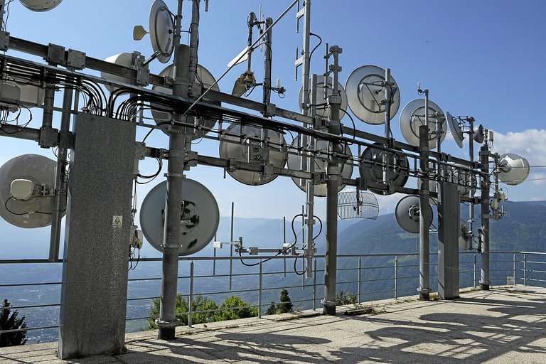
The upper limit of ionospheric propagation varies with the sunspot cycle, which goes through eleven-year cycles of activity. At periods of high sunspot activity, the upper frequency can reach 30 MHz. Above 30 MHz, radio waves travel mainly by space wave which is a line-of-sight wave. Both Earth-bound and satellite TV use this mode of propagation. The range is then limited by the curvature of the Earth. At these frequencies, the ionosphere has little effect.
DIGITAL COMMUNICATIONS
It is now possible to send a complete message over the radio that takes only milliseconds to transmit. Signals can also be coded so that only the person they are intended for can receive them. This system is called packet radio and has been used for about twenty years by radio amateurs and for longer by military and commercial users. In packet radio, the transmitted signal is converted to a series of very short pulses which are compressed together into a very short period of time, usually only milliseconds. These signals are computer messages, pages of text compiled and decoded by a computer at each end.
Personal computer-based videophones allow us to communicate face to face. We can have video conferences with each person seen in their window on the monitor screen. Communication from computer to computer over the internet has become a part of our everyday lives. Many of us send text messages to our friends over our mobile and through the use of e-mail. These are just some of the changes that have been made possible because of digital systems. In using them. Communications technology has surprisingly reverted to the first effective electrical method used to transmit information, that is, Morse code, which consists of a series of short and long pulses.
A pulse is made by switching the signal ‘on’ for a short time. In Morse code. Long pulses (dashes are three times as long as short ones (dots’). Combinations of pulses are used to represent letters, and these are strung together to make words and sentences. Samuel Morse devised his code to take advantage of the new wire telegraph that he invented in 1837. Messages could be sent over very long distances – the first transatlantic cable carrying Morse came into use in 1858, while the first transatlantic telephone line wasn’t laid until 1956. Digital transmissions are less affected by noise interference, they can travel further and still be detected, and they take up less frequency space, so that more stations can use the same band.
WHAT IS A DIGITAL CODE?
Morse code is a simple digital code. Electronic digital codes and digital signals are also very simple: they have only two values. They are either ‘on’ or ‘off’. A digital signal is made up from combinations of ‘on’ and ‘off’ pulses. ‘Off’ is given the code ‘0’ and ‘on’ the code 1.
The binary code
Simple code in common use is the binary code. The binary number system is based on just two digits, 0 and 1 (as compared to the ten used by the decimal system – 0 to 9). In a table showing what signals are equivalent to the binary codes for decimal numbers 1 to 15, the third column of the table shows each binary number represented as a four ‘bit’ binary word. Each digit of the binary number is called a bit (from binary digit). Zeros are added as extra bits to the left of any number that is less than four bits. Digital signals are made up from four-bit words or multiples of them: 8 bit (called a byte), 16 bit, 32 bit, or even 64 bit.
DIGITAL SIGNALS
Images and sounds are changed into digital codes, and the codes are transmitted as pulses. Then the receiver equipment changes the pulses back into the original sounds or images. Let us look further at this process. Digital signals are easy to receive. All the receiver needs to do is to detect whether a pulse is high or low. Digital signals, transmitted either as a radio signal or down a telephone line, tend to change after they have travelled some distance. A very regular pulse changes as it travels a long distance, but as long as the receiver can still distinguish between ‘high and ‘low’, the original signal can be reproduced accurately. Analogue signals do not have this abrupt ‘high-low’ pattern. They change continually and become corrupted over much shorter distances.
Older undersea telephone systems use special equipment that amplifies and reshapes the analogue signal. They are called repeaters and are required every 3 nautical miles. Moden digital systems which use optical fibres have repeaters every 30 nautical miles. The digital repeaters change the corrupted pulses, back into perfect pulses.
SIGNAL CONVERSION
Many signals that we wish to send start out as analogue signals. Examples are speech or music which change continually. To benefit from the advantages of a digital system, the analogue signal must first be changed into a digital signal.
This process is called analogue-to-digital conversion. The digital signal is then transmitted, and at the receiver, it is turned back into an analogue signal. This is called digital-to-analogue conversion. Ideally, the received signal should be a perfect reproduction of the analogue signal we began with.
PULSE CODE MODULATION (PCM)
There are several ways that signals can be converted into digital pulses. We will look at one of them, pulse code modulation or PCM, which is the method commonly used in communication systems.
In particular, let’s see what happens inside a digital telephone line using PCM.
Analogue-to-digital conversion
First, the microphone changes the sound of a voice into an electronic analogue signal which is an alternating voltage which varies over a range of voltages and frequencies. The signal travels in this form to a local telephone exchange where it is changed into a digital signal using PCM.
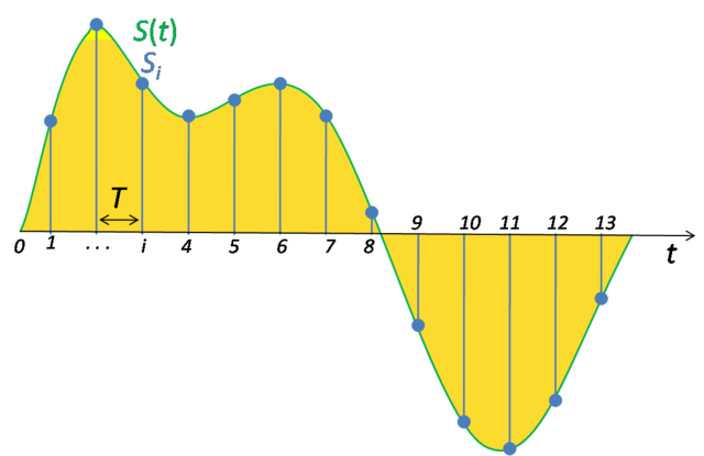
The voltage of the analogue signal is measured – it is sampled – several times during each cycle of the signal. The samples are very short, pulses of varying amplitude and taken together they show the same shape as the original analogue signal. The number of pulses per second is called the sampling rate.
The sampling rate will depend on the highest frequency present in the signal to be sampled and is related to it by a simple formula:
sampling rate ≥ 2 × (maximum frequency in signal)
In two digital pulses, we look for the most obvious simple signal that could be represented by these samples. The simplest signal is a sine wave. When lower frequency signals are sampled at the same rate there will be more samples for each complete cycle of the signal. Reconstructing these signals will be far easier and more accurate. For, example: digital telephone systems use the same practical rules as for AM, with a maximum audio frequency signal of 4 kHz. A sampling rate of 8000 times per second is twice that maximum frequency. When the signal has been sampled like this it is described as pulse amplitude modulated (PAM).
The next step is to convert the varying amplitude pulses into a binary code. The maximum analogue voltage, which depends on the microphone and the amplifier used, is subdivided into a fixed number of levels. This process is called quantisation and the levels are called quantisation levels. For example, if the maximum signal voltage is 1 volt, this would be the highest level. If sixteen quantisation levels were used, then the first level above zero would represent 1/16 volt. Each sampled pulse is then measured and matched to these levels and is given the value of the closest level. Each amplitude pulse is given a digital code which is a binary number. The size of the number, that is, how many bits it has, depends on the number of quantisation levels. If there are eight levels (including zero), then a three-bit code will do.
To summarise, the number of quantisation levels determines the number of bits in the code for each pulse. Each pulse is represented by a binary number with the same number of bits, no matter what its level and each binary number is called a word. All samples with a value in a particular range are given the same binary code.
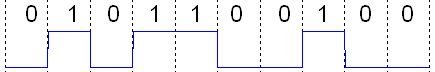
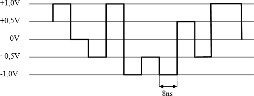
Each binary code is then transmitted in sequence, starting with the first sample. If the binary signal were displayed on an oscilloscope, it would look like a series of pulses, each having the same amplitude, but these pulses would now have different lengths. Each binary digit is allocated a fixed period of time. The length of the pulse is the time for which it is high or low. Binary zeros (0) are represented by zero volts, and binary ones (1) by a fixed voltage (often, +5 V is used). A series of several consecutive 1’s or 0’s represent a longer pulse. The signal is now pulse code modulated.
In a telephone system, these digitised pulses are transmitted along a coaxial cable, or they are converted into pulses of infrared radiation and sent along an optical fibre. They may even be transmitted as pulses of radio waves at microwave frequencies. The information from the Voyager space probes was sent back to Earth as a PCM radio signal.
Digital-to-analogue conversion
At the receiver, the process is reversed. As it arrives, each binary word is decoded by the receiver as the voltage equal to the mean of the relevant quantisation level. As the samples are decoded, they are reassembled to make the original analogue signal and the digital signal is changed back into a pulse amplitude modulated (PAM) signal. This is further processed to give the original analogue signal.
A five level PAM digital signal. Flominator, CC BY-SA 3.0
The quality of reproduction depends on the number of quantisation levels, that is how close together they are within the range used. More levels mean bigger binary codes. Larger binary codes can be sent within the same time by giving each binary digit a shorter time.
Till next time, I remain my humble self, @emperorhassy.
Thanks for reading!
REFERENCES
http://www.equestionanswers.com/notes/modulation-analog-digital.php
https://en.wikipedia.org/wiki/Modulation
https://www.britannica.com/technology/telecommunication/Modulation
https://www.rfwireless-world.com/Terminology/Advantages-and-Disadvantages-of-AM-and-FM.html
https://prezi.com/ng0ttkoeexuh/am-and-fm-limitations-and-benefits/
https://www.explainthatstuff.com/radio.html
http://www.qrg.northwestern.edu/projects/vss/docs/Communications/2-why-does-it-take-so-long.html
https://en.wikipedia.org/wiki/Radio_wave
https://en.wikipedia.org/wiki/Data_transmission
https://www.sciencedirect.com/topics/engineering/digital-communication-system
https://www.allaboutcircuits.com/textbook/digital/chpt-14/introduction-to-digital-communication/
https://www.tutorialspoint.com/computer_logical_organization/binary_codes.htm
https://en.wikipedia.org/wiki/Binary_code
https://www.disneystudioshelp.com/detail_HOWDOESDCWORK__DIGITALCOPYHELP.html
https://www.techwalla.com/articles/what-is-digital-coding
https://en.wikipedia.org/wiki/Digital_signal
https://www.chegg.com/homework-help/definitions/digital-signal-4
https://www.ia.omron.com/support/guide/63/introduction.html
This post has been voted on by the SteemSTEM curation team and voting trail. It is elligible for support from @curie.
If you appreciate the work we are doing, then consider supporting our witness stem.witness. Additional witness support to the curie witness would be appreciated as well.
For additional information please join us on the SteemSTEM discord and to get to know the rest of the community!
Thanks for having added @steemstem as a beneficiary to your post. This granted you a stronger support from SteemSTEM.
Thanks for having used the steemstem.io app. You got a stronger support!