Elektronikprojekt Teil 5 / Electronics project part 5
Hallo Elektronikfreunde.
Weiter geht es mit der Gleichrichtung.
Die wenigen Bauteile der Gleichrichtung sind der Gleichrichter und der Kondensator zur Glättung der Gleichspannung. Der Widerstand dient zur Entladung des Kondensators, wenn das Gerät ausgeschaltet wird.

Bild 01: Bauteile der Gleichrichtung
Hier ein Ausschnitt aus dem Schaltplan:
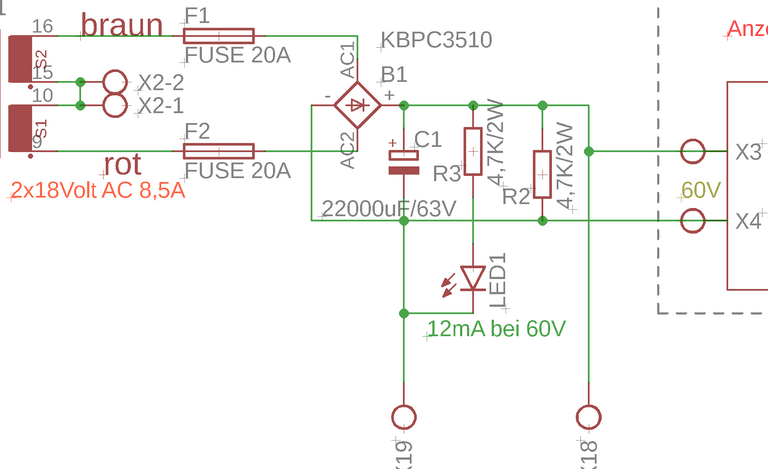
Bild: 02 Schaltplanausschnitt der Gleichrichtung
Der Gleichrichter ist ein 35Ampere-Typ. Trotzdem wird er auch bei 15A schon merklich warm, deshalb habe ich ihn auf einen Aluminiumwinkel montiert.
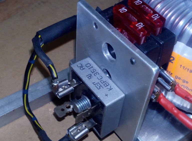
Bild 03: Gleichrichter KBPC 3510
Der Kondensator hat eine Kapazität von 22000uF und kann bis 63Volt Spannung vertragen. Je größer die Kapazität umso geringer die Restwelligkeit und umso weniger bricht die Spannung bei hoher Last zusammen. Hier sollte ein hochwertiger Typ mit 105°C Temperaturbelastbarkeit eingebaut werden. Natürlich lassen sich auch mehrere kleine Kondensatoren in Parallelschaltung verwenden. Wichtig ist die Spannungsfestigkeit von mindestens 63Volt!
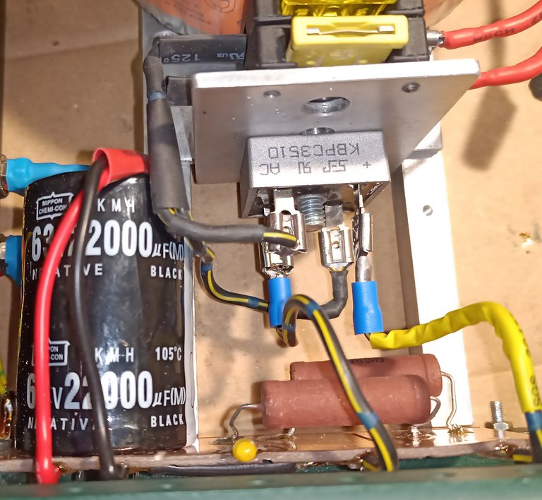
Bild 04: Gleichrichtung alle Komponeneten
Außerdem habe ich dem Entladewiderstand einen Zweiten mit einer LED parallel geschalten. Dies zeigt mir im Reparaturfall bei geöffnetem Gerät, wann der Kondensator entladen ist. Über die zwei Widerstände fließen etwa 20 bis 25 mA Strom. 1Watt Widerstände reichen rechnerisch aus, doch werden diese schon merklich warm. Ich empfehle 2W -Typen zu verwenden.
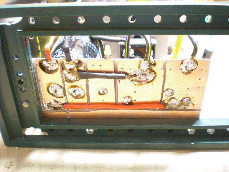
Bild 05: Leiterplatte
Den Kondensator, die Widerstände und die LED habe ich auf eine Leiterplatte montiert. Da die Verschaltung der Bauteile sehr einfach ist, habe ich mir das Ätzen und Entwerfen eines Layouts erspart und einfach mit einem kleinen Fräser, wie im Bild05 zu sehen, Quadrate ausgefräst. Das rote Kabel verbindet Kondensator Plus mit dem Plus des Gleichrichters.
Das schwarze Kabel verbindet Kondensator Minus mit Gleichrichter Minus. Die Kupferfläche in der Mitte ist der Anschluss für LED und Vorwiderstand LED. Also alles sehr einfach gehalten.
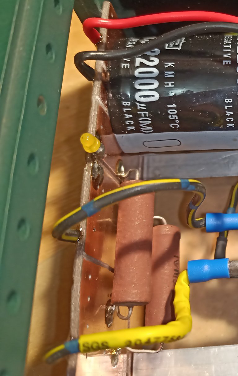
Bild 06: Leiterplatte Innenseite, die gelbe LED ist hier gut zu sehen.
Auf der anderen Leiterplattenseite sind ebenfalls die Kontaktflächen vorhanden da ich nur doppelseitig kaschiertes Material in der Bastelkiste hatte.
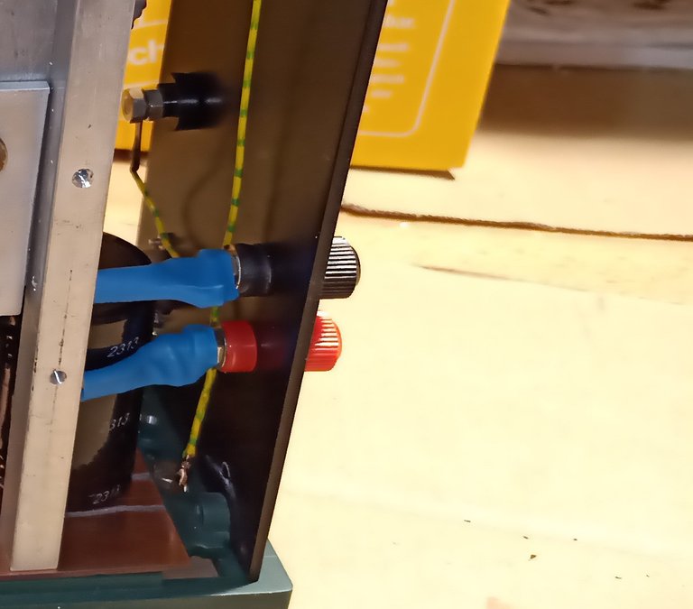
Bild 07: Anschlussbuchsen Rückseite
Die Anschlüsse X18 und X19 aus dem Schaltplan sind an der Rückseite des Gerätes (siehe Bild07).
Hier kann man die ungeregelte Gleichspannung die am Kondensator anliegt entnehmen. Das sind im unbelasteten Zustand ca. 56 Volt!
Für heute genug.
Fortsetzung folgt …….
google translator
Hello electronics enthusiasts.
It continues with the rectification.
The few components of the rectification are the rectifier and the capacitor for smoothing the DC voltage. The resistor is used to discharge the capacitor when the device is switched off.
Picture 01
Here is an extract from the circuit diagram:
Picture 02:
The rectifier is a 35 amp type. Nevertheless, it gets noticeably warm at 15A, so I mounted it on an aluminum bracket.
Picture 03: Rectifier
The capacitor has a capacity of 22000uF and can withstand up to 63Volt voltage. The larger the capacity, the less ripple and the less the voltage collapses under high load. A high-quality type with a temperature rating of 105 ° C should be installed here. Of course, several small capacitors can also be used in parallel. The dielectric strength of at least 63Volt is important!
Picture 04: Rectification
I also connected a second one with an LED to the discharge resistor. This shows me when the device is repaired when the capacitor is discharged. About 20 to 25 mA of current flow through the two resistors. 1Watt resistors are sufficient from a calculation point of view, but they are already noticeably warm. I recommend using 2W types.
Picture 05:
I mounted the capacitor, the resistors and the LED on a circuit board. Since the connection of the components is very simple, I saved myself the etching and designing of a layout and simply milled out squares with a small milling cutter, as shown in picture 05. The red cable connects capacitor plus with the plus of the rectifier.
The black cable connects capacitor minus to rectifier minus. The copper surface in the middle is the connection for LED and series resistor LED. So everything was kept very simple.
Picture 06:
On the other side of the circuit board there are also contact areas because I only had double-sided laminated material in the craft box.
Picture 07: Sockets on the back
The connections X18 and X19 from the circuit diagram are on the rear of the device (see Fig. 07).
Here you can see the unregulated DC voltage across the capacitor. That is approx. 56 volts in the unloaded state!
Enough for today.
Sequel follows …….
Du hast ein Upvote von mir bekommen, diese soll die Deutsche Community unterstützen. Wenn du mich unterstützten möchtest, dann sende mir eine Delegation. Egal wie klein die Unterstützung ist, Du hilfst damit der Community. DANKE!
Congratulations @qwertm! You have completed the following achievement on the Steem blockchain and have been rewarded with new badge(s) :
You can view your badges on your Steem Board and compare to others on the Steem Ranking
If you no longer want to receive notifications, reply to this comment with the word
STOPTo support your work, I also upvoted your post!
Vote for @Steemitboard as a witness to get one more award and increased upvotes!