Elektronikprojekt Teil 4 / Electronics project part 4
Hallo Elektronikfreunde.
Nachdem ich wegen dem defekten Netzschalter auf der Primärseite des Geräts nicht weiterkomme geht es heute um den Sekundärteil. Die 2 x 18Volt AC sind in Reihe geschaltet, so dass als Dauerleistung bei einer Trafoleistung von 300VA ca. 36Volt bei 8,3Ampere zur Verfügung stehen. Im Leerlauf sind es real ca. 41Volt!
Der Trafo ist recht schwer, darum war eine stabile Konstruktion in dem Gehäuse notwendig. Als Material kam Aluminium zum Einsatz welches auch entstehende Wärme gut ableiten kann. Der Trafo sitzt auf einem 4mm Starken Aluminiumblech welches wiederum durch 10mm Quadratstreben im Gehäuse gehalten wird. Außerdem ist die Konstruktion gleichzeitig zur Kühlung des Gleichrichters da, der an einem Aluminiumwinkel geschraubt wurde.
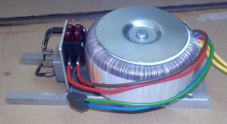
Bild: Trafomodul.jpg
Im Test der Komponenten hat sich gezeigt, dass sich der Trafo für ca. 30 Minuten mit 600VA belasten lässt. Das sind das rund 16 Ampere die entnehmbar sind. Bei Kurzschluss gibt das dann schon einen kräftigen Schweißfunken der an Metallen kleine Krater hinterlässt. Die im Bild zu sehenden 10 Ampere KFZ-Sicherungen wurden mittlerweile durch 20 Ampere Typen ersetzt. Ich habe für jeden Leiter eine Sicherung gewählt. Denkbar ist auch der Einsatz nur einer Sicherung zwischen grünem und blauem Leiter im gezeigten Bild.
Auch wenn 16 Ampere ein recht kräftiger Strom ist, reicht bei diesen kurzen Verbindungen ein Kabelquerschnitt von 2,5mm². Besser sind 4mm² die mir aber nicht zur Verfügung standen.
Außerdem wird das Netzteil in den Hauptanwendungen meist unter 5 Ampere belastet werden.
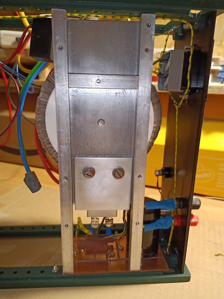
Bild: Konstruktion.jpg
Im Bild ist die Aluminiumkonstruktion zu sehen.
Noch einige Hinweise zu Aluminium.
Die meisten meinen, Aluminium zu verarbeiten ist einfach, da das Metall ja schön weich ist.
Genau das ist aber bei dickeren Werkstücken die Tücke. Aluminium „schmiert“! Das soll bedeuten das beim schnellem bohren, Wärme entsteht. Das Aluminium wird teigig (schmierig) und verklebt die Schneiden des Bohrers und verstopft die Spannut. Dünne Bohrer brechen schnell ab und stecken wie verschweißt im unfertigen Bohrloch. Beim Gewindeschneiden reißt oft das Gewinde aus oder ist sehr unsauber geschnitten da ganze Windungen ausbrechen.
Beim Bohren der 2,4mm Löcher für die M3 Gewinde ist also Sorgsamkeit geboten, denn hakt der Bohrer bricht er auch schnell ab. Um diesen Schmiereffekt zu mildern, benutzt man beim Bohren und Gewindeschneiden in Aluminium Rapsöl. Einfaches Öl geht natürlich auch ist aber nicht so schmierfreudig und umweltneutral.
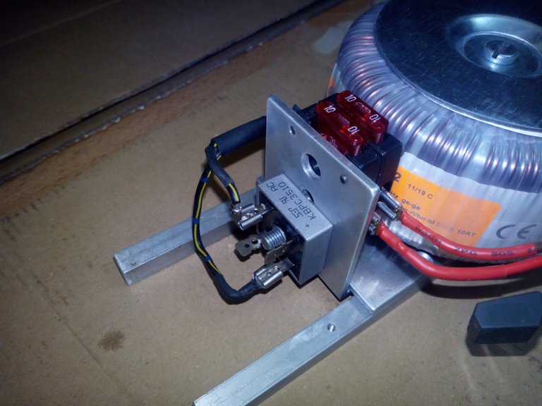
Bild: Ringkerntrafo mit Gleichrichter.jpg
Nun aber weiter mit dem Projekt.
Von den Sicherungen geht es mit zwei Kabel zum Gleichrichter. Die Anschlussbelegung des Gleichrichterblocks lässt sich im Bild erkennen. Dieser ist über 6,3mm Steckverbinder angeschlossen. Lieber hätte ich die Kabel direkt verlötet, jedoch lassen sich die Anschlüsse schwer löten da die Wärme schnell abgeführt wird und bevor ich schlechte Lötverbindungen habe, entschied ich mich für die Kabelschuhe. Das Problem ließe sich sicher noch besser lösen.
In das Mittelloch des Gleichrichters lässt sich problemlos ein M6 Gewinde schneiden. Natürlich kann man auch eine M5 Schraube nutzen um den Gleichrichter an das Kühlblech zu schrauben. Ich wollte aber zwischen den 4 Gleichrichteranschlüssen nicht noch eine M5 Mutter haben.
Das wars für heute.
Fortsetzung folgt …….
google translator
Hello electronics enthusiasts.
After I get stuck because of the defective power switch on the primary side of the device, today it's about the secondary part. The 2 x 18Volt AC are connected in series, so that about 36Volt at 8.3Ampere are available as continuous power with a transformer power of 300VA. In idle it is around 41 volts in real!
The transformer is quite heavy, so a stable construction in the housing was necessary. Aluminum was used as the material, which can also dissipate heat. The transformer sits on a 4mm thick aluminum sheet which in turn is held in the housing by 10mm square struts. The construction is also used to cool the rectifier, which was screwed to an aluminum bracket.
Image: Trafomodul.jpg
The test of the components showed that the transformer can be loaded with 600VA for approx. 30 minutes. That is around 16 amps that can be removed. In the event of a short circuit, there is already a strong welding spark that leaves small craters on metals. The 10 amp automotive fuses shown in the picture have now been replaced by 20 amp types. I chose a fuse for each conductor. It is also conceivable to use only one fuse between the green and blue conductors in the picture shown.
Even if 16 amps is a fairly powerful current, a cable cross-section of 2.5mm² is sufficient for these short connections. 4mm² are better, but they were not available to me.
In addition, the power supply in the main applications will usually be loaded below 5 amps.
Image: Construction.jpg
The aluminum construction can be seen in the picture.
Some more information about aluminum.
Most people think that processing aluminum is easy, since the metal is nice and soft.
This is exactly the problem with thicker workpieces. Aluminum "lubricates"! That should mean that when drilling quickly, heat is generated. The aluminum becomes doughy (greasy) and glues the cutting edges of the drill and clogs the flute. Thin drills break off quickly and, as welded, are stuck in the unfinished borehole. When tapping, the thread often tears or is cut very uncleanly because entire turns break out.
Care must be taken when drilling the 2.4mm holes for the M3 threads, because the drill quickly breaks off. To alleviate this smear effect, rapeseed oil is used for drilling and tapping in aluminum. Of course, simple oil is also not as easy to lubricate and environmentally neutral.
Image: Toroidal transformer with rectifier.jpg
But now continue with the project.
There are two cables from the fuses to the rectifier. The pin assignment of the rectifier block can be seen in the picture. This is connected via 6.3mm connectors. I would have preferred to solder the cables directly, but the connections are difficult to solder because the heat is dissipated quickly and before I have bad solder connections, I decided on the cable lugs. The problem could certainly be solved even better.
An M6 thread can easily be cut into the center hole of the rectifier. Of course you can also use an M5 screw to screw the rectifier to the heat sink. But I didn't want to have an M5 mother between the 4 rectifier connections.
That's it for today.
Sequel follows …….
According to the Bible, How does the kingdom of heaven suffer violence as it is written in the Bible? (Part 1 of 4)
(Sorry for sending this comment. We are not looking for our self profit, our intentions is to preach the words of God in any means possible.)
Comment what you understand of our Youtube Video to receive our full votes. We have 30,000 #SteemPower. It's our little way to Thank you, our beloved friend.
Check our Discord Chat
Join our Official Community: https://beta.steemit.com/trending/hive-182074
Congratulations @qwertm! You have completed the following achievement on the Steem blockchain and have been rewarded with new badge(s) :
You can view your badges on your Steem Board and compare to others on the Steem Ranking
If you no longer want to receive notifications, reply to this comment with the word
STOPTo support your work, I also upvoted your post!
Vote for @Steemitboard as a witness to get one more award and increased upvotes!
Du hast ein kleines Upvote von unserem Curation – Support – Reblog Account (German Steem Bootcamp) erhalten. Dieser wurde per Hand erteilt und nicht von einem Bot.
Du findest uns im Discord unter https://discord.gg/Uee9wDB
Vielen Dank für die Unterstützung.