How to control a drone remotely? Part 1: The Transmitter [Building a Quadcopter#3]
For the third article of this series devoted to the construction of a racing drone (or UAV, Unmanned Aerial Vehicle), we will talk about the remote control. What, how, and why, we will answer all these questions throughout the article!
Our needs:
Before detailing the solutions, we need to know what we need, so here are our requirements:
It is necessary to be able to control the 3 axes of rotation as well as the gases (the power of the motors).
Something to arm the UAV (arming meaning activating the engines) and change modes (stabilized/acro).
A communication protocol compatible with our flight controller
Have the place to put the receiver on the drone (and a receiver not too heavy)
A good range (500m to 1km minimum to ensure good reception in case there are obstacles that could attenuate the signal)
Frequencies and powers allowed in our country (this aspect will be more important for video transmission)
With these criteria on paper (or screen in our case), we will be able to go and see the different existing technologies.
Technologies on the market:
There is not a lot of them accessible to everyone, if we exclude Bluetooth because of its short-range (reliable up to 5m in general, it's more 20m currently) and the same for the ultrasound and infrared, moreover we can't (or with great difficulty) track the receiver so we can also rule out systems using narrow beams or very directional ones. The last technologies for us to look at is the electromagnetic waves used for long distances (such as wifi and radio waves for example).
Why should we use these electromagnetic waves?
First of all, let's start from the basics, what is a wave?
Waves are often described as a disturbance that propagates like ripples when a body (or a pebble) is thrown into water :

We can characterize (very simply) a wave by using 3 criteria:
- Its type: mechanical, electromagnetic or gravitational
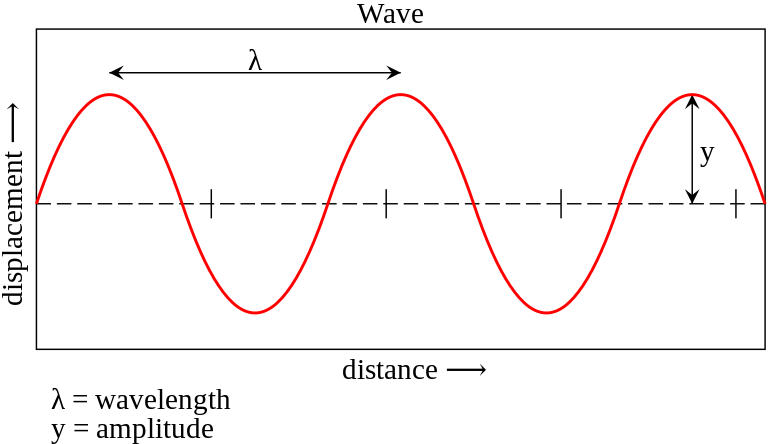
- Its wavelength: the distance in m between 2 repetitions, for example between two peaks of a sinusoid.
- Its amplitude: half of the difference in height between the highest and lowest points.
The radio and Wifi waves have long wavelengths (up to one kilometer) and are well after the red and infrared, so they are not disturbed by medium-sized obstacles :

Indeed, when an electromagnetic wave encounters an obstacle smaller or as large as its length, it tends not to be disturbed too much (the amplitude decreases but the signal is still perceived). Then the bigger the obstacle becomes in relation to the wavelength the more difficult the transmission will be and when the obstacle is about 100 bigger than the length it is almost impossible to establish a transmission. (If you want more details about the propagation of radio waves I recommend you to take a look at this NASA's Tour of the Electromagnetic Spectrum and theses resources)
In our case the waves we will use have frequencies of 2.4 and 5.8 GHz. The wavelength being equal to the speed of light, c in m/s, divided by the frequency f in Hz (λ=c/f), we obtain wavelengths of about 12cm ( 299792458/(2.4(10^9)) ) and 5.2cm. Thus we can hope to establish a transmission between the transmitter and the receiver even when there is an obstacle of about 12m (for 2.4Ghz) or 5m (for 5.8 GHz). Perfect for our use in fields!
Usually, 2.4Ghz is used for remote control and 5.8Ghz for video transmission, this allows to keep control when some obstacles momentarily block the 5.8Ghz but not the 2.4Ghz.
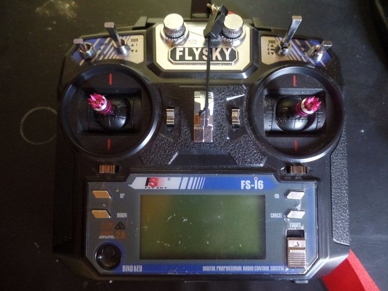
How does the remote control work?
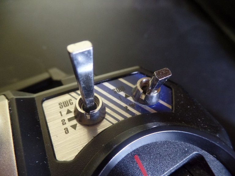
Concerning the remote control itself, we will use one with 2 joysticks and several switches. The joysticks will control the 3 axes of rotation of the UAV as well as the power of the engines and the switches will be used to perform different actions that we will configure later (we can for example "arm" the quadcopter, i.e. switch on the engines, switch from one flight mode to another, etc...).
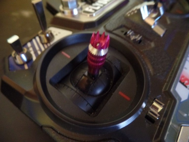
The joysticks:
First of all, we have to ask ourselves what a joystick is made of. If you've ever used one for DIY projects or if you've ever broken/disassembled a joystick you may have already noticed, a joystick is capable of rotating on two axes (x and y, up-down and left-right).
On these axes are attached potentiometers, these are components whose resistance can vary (usually you can vary this resistance by turning a knob or moving a slider) :
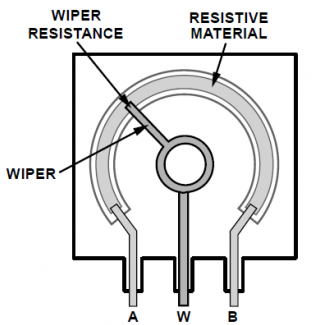
Source: Sunfounder
We will be able to use this property to read the angle at which the joystick is on each of the 2 axes. Indeed, if we apply a 5V voltage to the terminals of a potentiometer we will be able to read a voltage proportional to the movement. But before we are going to take a very quick look at resistors :
Resistors:
A resistor is an electrical component whose purpose is to oppose the passage of current. Very used in electronics (you will come across them everywhere), they are present in a formula that you may know, the famous Ohm's law: U=R x I which relates the voltage, resistance and current passing through it:

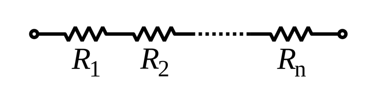
Using the analogy of water, the resistance (the component) could be a constriction of a river, the voltage would be the difference in water level at the ends of the constriction, the current would be the electric current flowing through the component, and the resistance would be defined by the constriction. We have already seen in the previous article how a battery behaves when cells are connected in series or in parallel, we will find similar characteristics for the resistors. For example, if you connect 2 resistors in series :
The resistors add up, i.e. if you have chosen resistors from 100Ω each, you will get one resistor from 200Ω at the terminals of the set.
And if you put them in parallel, it's the inverses that add up, also called conductance (1/Req = 1/R1 + 1/R2 + ..., Req means Equivalent Resistance, i.e. the resistance of the circuit):
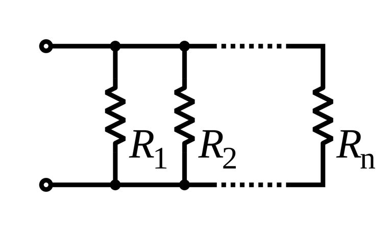
For example if we take our 100Ω resistors and put them in parallel we get: 1/Req = 1/100 + 1/100 = 2/100 = 1/50 so Req = 50 Ω
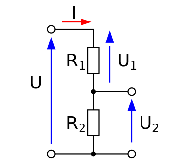
Let's come back to our potentiometers, when it doesn't move we can represent it in this way, using 2 resistors. As we have said above, the total resistance is equal to the sum of the 2 resistors. So when we move the knob, the values of the resistors evolves but the sum remains unchanged. In this way we can use the principle of the voltage divider (a circuit allowing to divide the input voltage with the help of 2 resistors, see diagram below) to read the evolution of the potentiometer position :
The formula used for this type of montage is as follows:
The letter U is used to represent the voltages, R the resistances and I the currents.
It can be read as follows: "The output voltage (Us) is equal to the resistance of the second resistor divided by the sum of the resistors all multiplied by the input voltage (Ue)".
In the case of a potentiometer, each of the 2 resistors varies between 0Ω and it's maximum (generally 10kΩ, 10 000Ω), so the voltage on the cursor will vary between 0V and the input voltage in proportion to the angle of the potentiometer. It is therefore possible to read the position of the joystick by reading the voltage of the 2 potentiometers, which is very simple with microcontrollers such as Arduinos for example.
Example showing how to read the position of a joystick with an Arduino
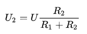
If you buy joysticks for DIY projects you can find them in this form:
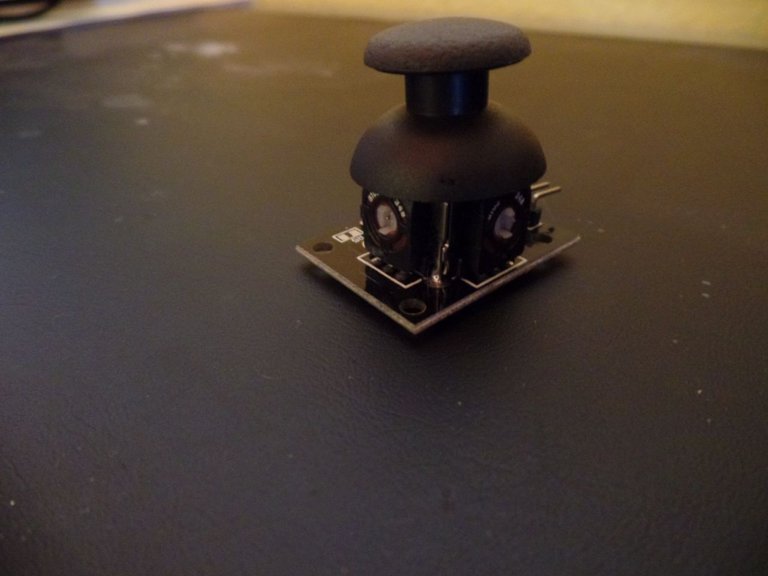
There are five pins:
Power supply (5V in my case) and ground (GND).
The 2 sliders of the potentiometers
And the push button (this pin is connected to ground when the button on my module is pressed)
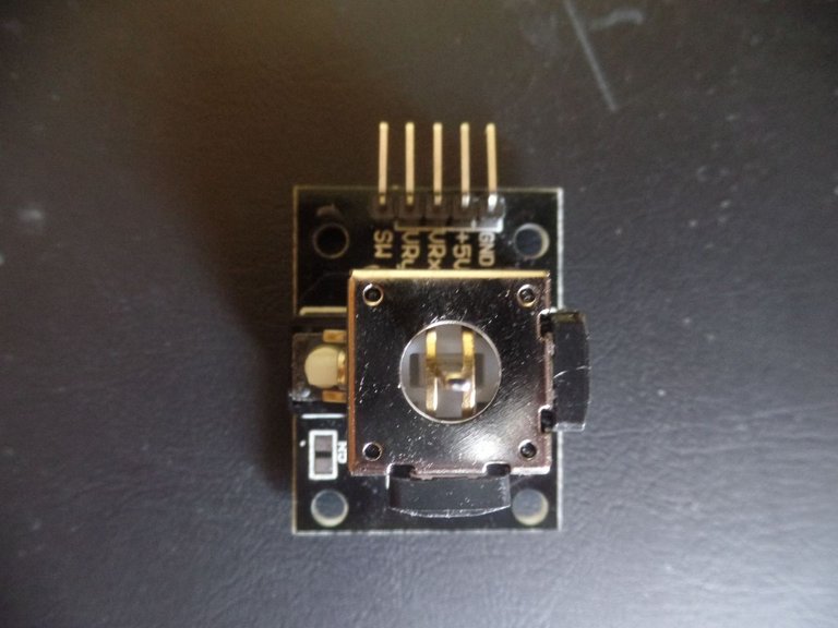
To use it with your Arduino we will make a very simple assembly.
Connect the 5v and ground of the joystick to the 5v and ground of your Arduino. Then connect the VRx to pin A0 and VRy to pin A1. You can also connect SW (the button pin) to pin D2 but we won't use it today.
Then send this program to read the 2 cursors and display the values on the serial plotter :
#define X A0 // X-axis of the joystick, blue on the serial plotter
#define Y A1 // Y-axis of the joystick, red
void setup() {
// put your setup code here, to run once:
pinMode(X,INPUT);
pinMode(Y,INPUT);
Serial.begin(9600); // Initiates communication with the computer in order to send the different values.
}
void loop() {
// put your main code here, to run repeatedly:
Serial.print(map(analogRead(X),0,1024,0,100)); // We read the value of the potentiometer linked to the X axis over 8bits (we obtain a value between 0 and 1024 which is then transformed into a percentage by the map function).
Serial.print(" "); // We send a space to separate the variables to be displayed
Serial.println(map(analogRead(Y),0,1024,0,100));
// We use println instead of print because we don't only want to display the variable but also to go back to the line at the end
delay(10); // Wait 10ms
}```
And here is the result when I move the joystick on one axis after the other (you can access the serial plotter by clicking on "tools" then "serial plotter" on the Arduino IDE):
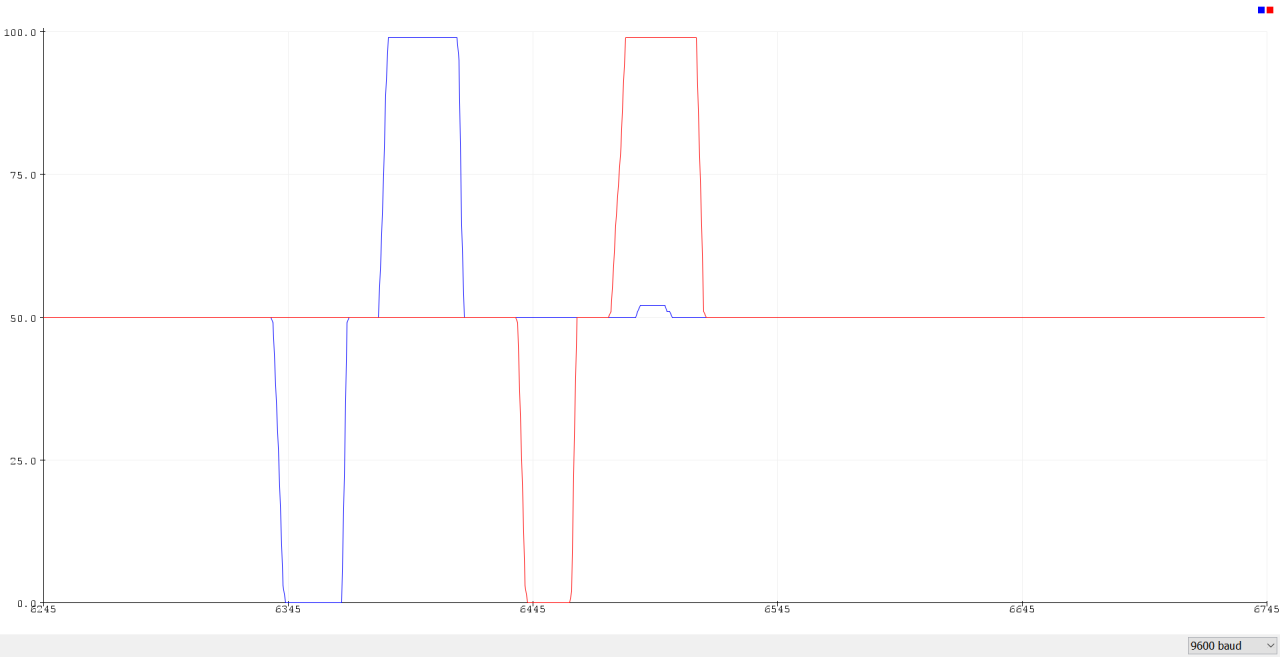
I have chosen to display the values in the Serial plotter but once you have retrieved the values you can do whatever you want with them (control a robot, a drone, a game, switch on LEDs,...), it's up to you!
These data are read by the remote control in a similar way, classified by channels (one channel containing one of the information) and then sent to the receiver that we will discover in the next article!
On that note, see you soon for a new article!
Thanks for reading me :)
## Series Summary:
- [#0: Introduction](https://peakd.com/steemstem/@robotics101/en-new-series-building-a-quadricopter)
- [#1: How to fly ?](https://peakd.com/steemstem/@robotics101/en-how-to-fly-building-a-quadcopter-1)
- [#2: What is Electricity and Understanding the Batteries](https://peakd.com/steemstem/@robotics101/what-is-electricity-and-understanding-the-batteries-building-a-quadcopter-2#)
# Going further:
- [NASA's Anatomy of an Electromagnetic Wave](https://science.nasa.gov/ems/02_anatomy)
- [Antennas & Propagation - Electronics Notes](https://www.electronics-notes.com/articles/antennas-propagation/)
- [CYMATICS: Science Vs Music - Nigel Standford](https://www.youtube.com/watch?v=Q3oItpVa9fs)
# Sources:
- [FRENCH] [Quelques aspects de la propagation des ondes radioélectriques](https://journals.openedition.org/tem/1447) by [Bernard Démoulins](https://journals.openedition.org/tem/1468)
- [Antennas & Propagation - Electronics Notes](https://www.electronics-notes.com/articles/antennas-propagation/)
- [Wireless communication](https://en.wikipedia.org/wiki/Wireless) and [Radio Waves - Wikipédia](https://en.wikipedia.org/wiki/Radio_wave)
- [List of 2.4 GHz radio use](https://en.wikipedia.org/wiki/List_of_2.4_GHz_radio_use)
- Figures from [Voltage Divider - Wikipédia](https://en.wikipedia.org/wiki/Voltage_divider)
Congratulations @robotics101! You have completed the following achievement on the Hive blockchain and have been rewarded with new badge(s) :
You can view your badges on your board And compare to others on the Ranking
If you no longer want to receive notifications, reply to this comment with the word
STOPTo support your work, I also upvoted your post!
Support the HiveBuzz project. Vote for our proposal!
@tipu curate
Upvoted 👌 (Mana: 21/28)
Thanks for your contribution to the STEMsocial community. Feel free to join us on discord to get to know the rest of us!
Please consider supporting our funding proposal, approving our witness (@stem.witness) or delegating to the @stemsocial account (for some ROI).
Thanks for using the STEMsocial app and including @stemsocial as a beneficiary, which give you stronger support.
Nice work. But your formatting has gone wrong in the final part I guess. I used to try these sorta stuff in my young age. :) Controlling motors via parallel port, AVR, PIC microcontrollers, etc.
Thank you! Oh hive.blog doesn't display it like stem.openhive.network, I will try to fix it.
Nice, we are doing a lot of this as well, are you still working in this field or have you completely switch to Computational Biology?
I am not working in this field. But I might do hobby stuff. Dont know when.. :)
I hope you are going to show us what you do if you start a project :)
Thanks for those details. I was always attracted by those drones, but not enough to buy one and try it out. After reading this... well I am still attracted, but not enough ^^
My offer to try mine out still stands (as soon as I fix it, apparently drones like mine don't like to go through a tree at high speed...) :)
Great! I however do not know when I will be visiting Strasbourg in a close future (I was supposed to be around last May... but... well you know ;) ).