Understanding Passive Filters with Experiment
Introduction
Filters have become increasingly important in signal processing in recent years. Filters have found applications in fields such as seismic data analysis and adaptive signal filtering in noisy communication networks. Filters are critical components of many systems, particularly communication and instrumentation systems. A filter allows one frequency band to move while rejecting another. Typically, one of two systems is used: passive RLC filters or active RC filters.
Passive filters are an important component that connects power electronics-based generation or electrical loads to the power grid. A voltage-source converter, for example, requires an output filter inductor in order to be powered and regulated. The sum of current harmonics is determined by the size of the inductance, which has an impact on the expense, size, and performance of the overall converter device. A very large inductance produces an effective, but bulky and expensive, passive filter. A lower inductance, on the other hand, means higher power losses (due to increased harmonic current), but at a lower size and expense.
Proper voltage distortion limit output requirements have a direct effect on filter architecture. Stringent harmonic requirements can necessitate the use of cumbersome and expensive passive filters, while more permissive specifications can result in harmonic stability issues due to insufficient filtering and reduced damping. Harmonic instability issues are exacerbated by series and parallel resonances in passive filters and grid impedance. It has been discovered that the incorrect selection of passive filter parameters, as well as the processing delay in the control system, are the main factors that can contribute to harmonic instability.
Passive filters work well at high frequencies, but at low frequencies, the necessary inductors are massive, bulky, and non-ideal. Furthermore, inductors are difficult to manufacture in monolithic form and are incompatible with many industrial assembly systems. Op-amps, resistors, and capacitors are used in active RC filters, which are made using isolated, thick film, and thin-film technologies. The efficiency of these filters is constrained by the performance of the op-amps.
When creating a filter, one or more elements must be changed in order to change the frequency response of the filter. Elements such as resistors and low-valued capacitors may be varied mechanically or by using specialized devices such as raysistors and varicap diodes. These methods present practical issues, particularly where high precision is required. Filters are mostly used in telecommunications and biomedicine. The requirements of the telecommunications industry and continuous technological growth impose. On the transceiver side, the filtering (active and passive) contributed significantly to the transceiver's reconfigurability and small size.
Experiment with RC Low Pass Filter
A simple passive RC Low Pass Filter, or LPF, can be easily constructed by connecting a single resistor and a single capacitor in series. We apply the input signal to the series combination, but we measure the output signal across the capacitor. The aim of the RC Low Pass Filter is to limit the frequency of the signal that passes through the circuit to a specific range. Typically, low pass filter allows low frequency signal to pass through. Hence F= 1/2𝝅 RC, the frequency that can be manipulated by changing the values of the resistor and capacitor to fit our needs. As a condition, the greater the value of resistance and capacitance, the greater the frequency range that can pass through.
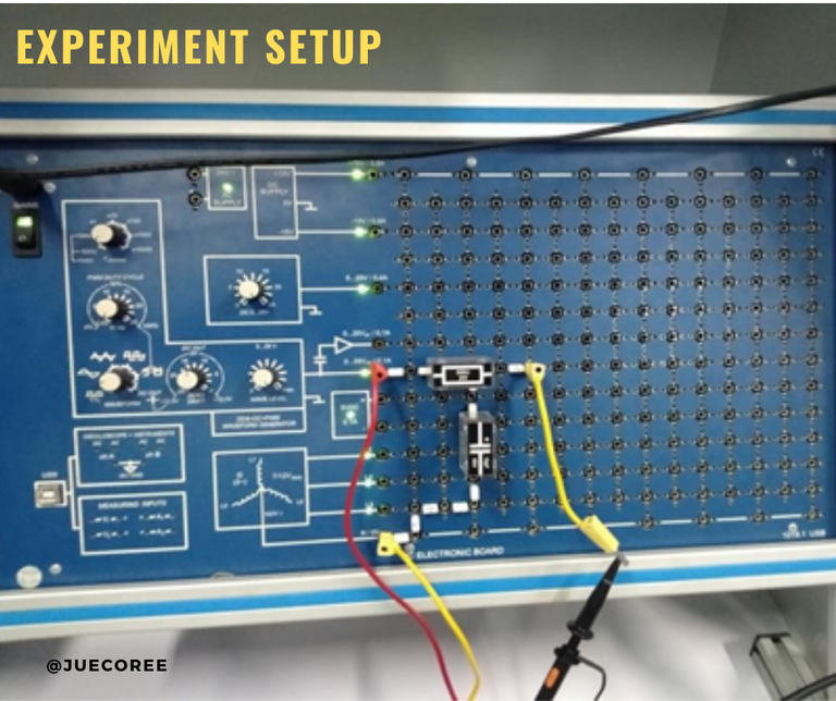
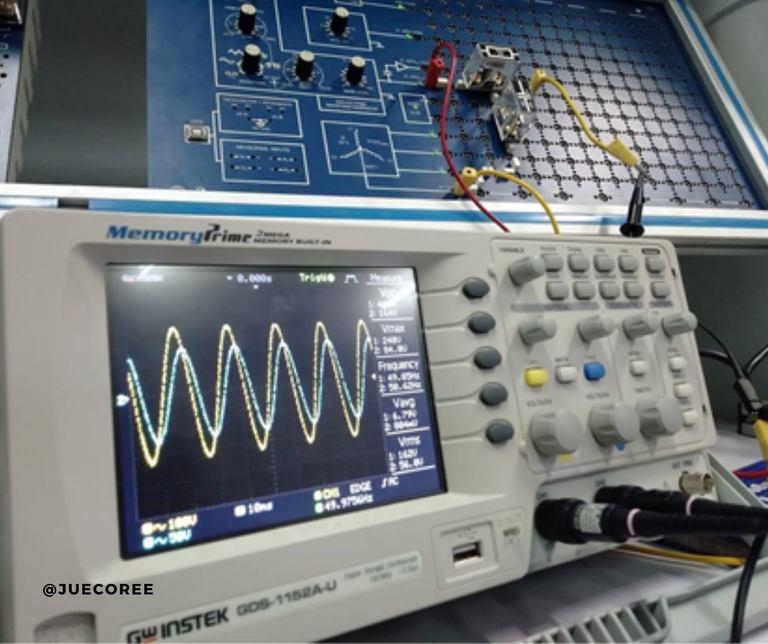
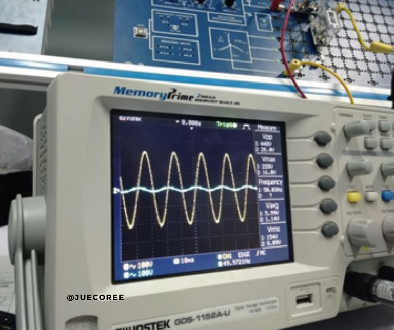
In the experiment, we placed a resistor with a resistance of 330 ohms and a capacitance of 10 microfarad. As calculated, the fundamental frequency is 53.03 Hertz. We can expect that signals with frequencies higher than the fundamental frequency can't pass through. We started with an input signal with 50 Hertz, and it successfully passes through the filter. It is shown in the signal registered in the oscilloscope.
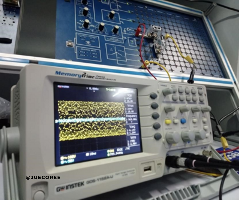
On the other hand, a signal with 1000 Hertz was not able to go through the filter. The process of changing the frequency of the input signal enable us to verify the response of an RC low pass filter. In the image below, we can observe a straight line in the oscilloscope. It is due to the output is not detected. I means that the 1000 Hertz signal was not able to course through the filter.
Low-pass filters are the most commonly used type of filter. We can set up several different circuit configuration to achieve our intended frequency, source and load impedances. We should remember that a filter with very low cut-off frequency is prone to attenuation.
Experiment with RC High Pass Filter
An RC high pass filter is the inverse of that of an RC low pass filter in that the low pass restricts the frequency to a range below the set range, while this filter allows frequencies higher than the set range to pass through. Using F= 1/2 RC, we can determine the fundamental frequency of the filter. This formula indicates that the greater the resistance and capacitance values, the greater the frequency range needed before frequencies can pass through. As you might have noted, it has similar computation to the RC low pass filter with respect to its frequency.
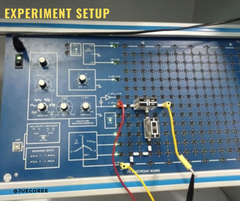
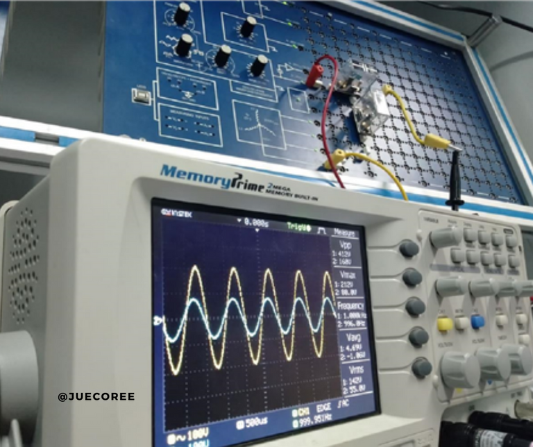
In the experiment, we set the resistor to a value of 33 ohms and a value of 10 micro-farad. When we replaced the frequency of the RC high pass filter in the formula, we got a frequency that had to be higher than 482.28 Hertz. It's essentially just reversing the capacitor and resistor positions on the first schematic diagram of the RC low pass filter. The oscilloscope was then connected to measure the input and output frequencies. When we set the input signal to 50 Hertz. The oscilloscope shows no reading on the output. It means the signal with 50 Hertz was filtered out.
A signal with 1000 Hertz, on the other hand, was able to pass through the filter and thus exceeded 482.28 Hertz. We looked at other frequencies and found the same result. Signals with frequencies lower than the fundamental frequency are not allowed to enter, but signals with higher frequencies are not filtered. We can see an output signal in the oscilloscope in the picture below.
High pass filters are commonly used in audio amplifiers to mediate the two audio amplifier levels, and in speaker systems. It is to direct higher frequency signals to smaller speakers while blocking lower bass signals. Besides, it is used to eliminate low frequency noise or distortion in the audio signal.
References
- Boylestad and Nachelsky, Electronic Devices and Circuit Theory
- Floyd, Electronics Fundamentals. Circuits, Devices, and Applications
- Schultz, Grob’s Basic Electronics
Note: All images are from the author except with separate citation.
Congratulations @juecoree! You have completed the following achievement on the Hive blockchain and have been rewarded with new badge(s) :
You can view your badges on your board and compare yourself to others in the Ranking
If you no longer want to receive notifications, reply to this comment with the word
STOPTo support your work, I also upvoted your post!
Check out the last post from @hivebuzz:
Support the HiveBuzz project. Vote for our proposal!
Yay! 🤗
Your content has been boosted with Ecency Points, by @juecoree.
Use Ecency daily to boost your growth on platform!
Support Ecency
Vote for Proposal
Delegate HP and earn more
Thanks for your contribution to the STEMsocial community. Feel free to join us on discord to get to know the rest of us!
Please consider supporting our funding proposal, approving our witness (@stem.witness) or delegating to the @stemsocial account (for some ROI).
Please consider using the STEMsocial app app and including @stemsocial as a beneficiary to get a stronger support.