ALTERNATING CURRENTS AND ELECTRICAL POWER
Introduction: Electricity generation in the UK.
In 2006/7 the UKs electricity consumption reached 48 000 GWh or about 1.3 × 10¹⁸ joules of energy. This energy is supplied to about 28 million consumers, factories, hospitals, schools and homes over the National grid.
The National Grid is a huge assembly of equipment: cables, pylons, transformers connecting the power stations to the consumer. There are 7000 km of overhead, high voltage cable supported by about 20 000 pylon plus over 500 km of underground cable.
The UK has a diverse range of power stations providing a total ‘installed’ capacity of 76.4 GW. In recent years the peak demand has reached about 60 GW. This can still stretch the system because, at any time, some generator will be off line being serviced. Large power stations may have three or four generators, but at any time one may be out of use or servicing, or just on standby.
Managing the distribution of energy on the Grid is a complex business. Prediction of demand is essential. Daytime demand is twice as high as at night, and the maximum demand in winter is four times the minimum in the summer. Major events such as international sporting events can increase demand by 10%. Extreme weather conditions can also create extra demands and are often difficult to predict.
Today, the UK Grid is connected to the continent via France. This offers extra flexibility for the planners and a market to sell our excess energy when we have it. In 2007/8 about 2000 MW of capacity was used in this way.
As non-renewable sources run out and because burning fossil fuels adds to greenhouse gases, there will be more emphasis on using renewable energy sources. Although some of these sources, such as wind, have increased in recent years, they are still unreliable and have not proved that they can provide energy on the scale our society demands. In the UK we have some large-scale renewable sources in the ‘pumped storage schemes such as Dinorwig in North Wales and Ben Cruachan in Argyll. These have the advantage that they can be switched on when demand is high and can be used to store the excess energy produced by other power stations at other times.
In all, there are over 250 power stations, large and small, ‘plugged’ into the National Grid. These range from large coal and nuclear stations to small wind farms and biofuel plants. Together, these are managed so that the system can with a frequency of 50 Hz ( ±1%) and a voltage of 230 V(±6%); that is, between 216 and 240 volts.
The system is designed to do this as efficiently as possible. In 2007/8 the total energy losses came to a mere 2.16% of the demand, or put another way, the system was very nearly 98% efficient.
The ideas in this post
Alternating currents play a very important role in electronic and physical systems. A microphone converts sound, caused by vibrations in the air, into an alternating current signal. When a loudspeaker is connected to an alternating current supply, it converts the signal back into sound. The electromagnetic waves radiated from a transmitting aerial are created by alternating currents and the signal picked up by a receiving aerial is converted into an alternating current. The speed at which a computer carries out instructions is determined by the frequency of alternating current created by the vibration of a tiny quartz crystal.
On an average day, the output of power stations in the UK is over 50 gigawatts and the energy generated is carried by alternating currents to the consumer. The nature of alternating current circuits is important to our understanding of the National Grid distribution system.
In this post, I will also consider how basic components like capacitors and inductors behave in a.c. circuits, so that we can understand the role they play in communications systems such as radio, in separating information from the ‘carrier’.
ALTERNATING VOLTAGES AND CURRENTS
The ‘voltage’ from a battery is direct – that is, it drives a steady or direct current (d.c.) around a circuit. This means that the charge flows in one direction. The current (or voltage) does not change with time. This is an idealized situation since in reality, the current from a real battery would gradually get smaller as the battery ‘runs down’.
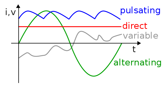
The electrical energy we get from the ‘mains’ is an alternating voltage. It drives an alternating current (a.c.) around a circuit. An alternating current is continually changing direction: see the figure below, which shows a typical current in a mains circuit.
Alternating current shows a distinctive waveform that is continually repeated: the graph shows three complete cycles of the pattern. The pattern of the a.c. mains is repeated 50 times every second – it has a frequency of 50 Hz. One cycle takes one-fiftieth of a second or 0.02 s. This time is the period of the waveform.
Another important characteristic of the waveform is that each cycle has a positive half-cycle and a negative half-cycle. During the positive half-cycle, the current is in one direction; during the negative half-cycle, the current direction is reversed.
The alternating current produced by a dynamo or generator varies in a very precise way – the current varies as a sine wave because of the way it is made by a spinning coil. That is, where I0 is the maximum current and f is the frequency of the current:
I = I0 sin 2πft
POWER IN A.C. CIRCUITS
Using two simple circuits in which a bulb is lit from an a.c. supply and from a d.c. supply as an instance. In each case the supply delivers energy to the bulb; the bulb gets hot and emits light.
In the d.c. circuit the energy transferred in the bulb each second (the power) can be found easily by using the equation:
Power = p.d. × current
Energy is also transferred in the a.c. circuit. However, there is a problem if we try to use the same equation. If the current and voltage are continually changing, which value of current and voltage do we use? The peak values are reached only twice each cycle. What about the average value? What is the average value of current or voltage over a complete cycle?
The answer is zero! The positive half-cycle is cancelled by the negative one. There is a solution: instead of current, we consider power. In a simple circuit like this, the current and voltage vary together, increasing and decreasing in time with each other. We say they are in phase with each other. If we multiply the value of the current at any instant by the corresponding voltage, we get the power at that same instant in time.
Since the current and voltage shown are sine waves, the corresponding power is a sine-squared wave. Notice that when the current and voltage are both negative the power is positive – the power is always positive, even though it is still varying. You can see from the graph that the average value for power is not zero. In fact, it works out that the average value of sine-squared is half of the maximum or peak value:
average power = ½ × peak power
= ½ × (peak current × peak voltage)
= (1/√2 × peak current) × (1/√2 × peak voltage)
= r.m.s. current × r.m.s. voltage
Where:
r.m.s. current = 1/√2 × peak current
r.m.s. voltage = 1/√2 × peak voltage
The ‘r.m.s.’ alternating current and voltage are actually equal to the steady, direct current and voltage which transfer the same amount of energy in the bulb. The abbreviation r.m.s. stands for root mean square. It refers to the square root of the mean of the squares of the current or voltage at every instant. The mathematical idea used here is: ½ = 1/√2 × 1/√2.
Also:
Peak current or voltage = √2 × r.m.s. value
= 1.4 × r.m.s. value
R.M.S., CAPACITORS AND WORKING VOLTAGES
The voltage stated for power supplies is usually the r.m.s. voltage. When using a capacitor we have to be sure not to exceed the working voltage of the capacitor. In d.c. circuits it is wise not to use voltages over about two-thirds of the rated working voltage of the capacitor. With a.c supply, we have to be even more careful.
For example, suppose a capacitor has a working voltage of 16 V. If such a capacitor were used in a circuit operated from a 9V d.c. supply we could be confident that it would behave well as a capacitor. However, if we have a 9V alternating voltage across the same capacitor, the peak voltage across it would be (9 × 1.4) or 12.6 V. This is still below 16 V but is about 2 V over two-thirds of 16 V, which is 10.7 V. It would be better to use a capacitor with a higher rated working voltage.
DISTRIBUTION OF ELECTRICAL ENERGY – THE NATIONAL GRID
The National Grid is the system used for distributing electrical energy around the country. It is a large and very complex circuit through which the power stations feed energy into every home, factory, hospital, and school. The size of the circuit creates problems. In more remote parts of the British Isles, consumers may be up to a hundred miles from the nearest power station. Cables of that length have substantial resistance. A current in these cables heats them – there is resistive heating. This unwanted heating is lost energy, wasted energy that does not reach the consumer.
These energy losses are often called I2R losses since, in a cable of resistance R carrying a current, the resistive power loss is I2. The fact that the power loss is proportional to I2 is significant: it means that halving the current reduces the power lost by a factor of four. This fact plays an important part in the design of the National Grid – electricity is transferred at high voltages so that currents can be kept small for a given power load. Transformers are used to increase and decrease voltages.
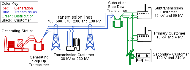
The largest modern generators produce electricity at 25000 V. Heavy industries use electricity at 33 000 V while lighter industries use it at 11 000V. Smaller users such as our homes use electricity at 230 V. Electricity is transmitted around the country at much higher voltages – 132 kV, 250 kV, and 400 kV.
One of the advantages of generating electricity as an alternating current is that transformers change a.c. voltages easily and efficiently (large transformers are typically about 99 percent efficient). Step-up and step-down transformers are used throughout the system to change voltages to obtain the required voltage.
Electricity in industry
Many industries that depend on electricity require vast amounts of energy. Take, for example, the large-scale production of aluminium, which is produced electrolytically from molten aluminium oxide obtained from the ore bauxite. The process requires a d.c. supply at nearly 1000 V and currents of 70000 A. The d.c. voltage is derived from the secondary coil of a step-down transformer, which we will assume gives a secondary voltage of 1000 V. We can make some estimates of the turns ratio and primary current in the primary coil of the transformer.
Let us assume 100 per cent efficiency. The factory is connected to the National Grid via a local substation that gives an output voltage of 33 000 V. The required turns ratio would be:
While the voltage is being stepped down, the current will be stepped up in the same ratio. That is:
This gives:
This is still a large current, but far smaller than the 70 000 A needed to produce the aluminium. This example is quite typical of many heavy industries that need electricity supplied at such large voltages.
Till next time when I further on this topic, I remain my humble self, @emperorhassy.
References
- Energy Consumption in the UK (ECUK) 1970 to 2018
- Electricity generation
- Electricity sector in the UK
- Energy in the UK
- UK electricity generation
- AC vs DC
- Alternating current
- Alternating current; Wikipedia
- What is alternating current?
- Electric power
- Power in an ac circuit
- Reactance-inductive-and-capacitive
- Ac circuits; rms voltage
- Capacitor
- Electricity-transmission uk
- Electrical_grid; Wikipedia
- National-grid-and-what-it-does
- Electricity industry
- Electric_power_industry
Greetings friend good article, I do not have much to contribute on the subject, but I call my attention because in country Venezuela the national electricity network currently goes through very difficult times, and some areas of the country tend to ration electricity for several hours because it does not generate enough energy.
I observe the diversification that exists in the national electricity network that you mention, there are many alternatives some better than others but seeing them as a whole there is an ideal complement to keep the system always active.
So long, my friend, have a great week!
Thanks for your contribution to the STEMsocial community. Feel free to join us on discord to get to know the rest of us!
Please consider supporting our funding proposal, approving our witness (@stem.witness) or delegating to the @stemsocial account (for some ROI).
Thanks for using the STEMsocial app, which gives you stronger support. Including @stemsocial as a beneficiary could yield even more support next time.
Congratulations @emperorhassy! You have completed the following achievement on the Hive blockchain and have been rewarded with new badge(s) :
You can view your badges on your board and compare yourself to others in the Ranking
If you no longer want to receive notifications, reply to this comment with the word
STOPDo not miss the last post from @hivebuzz: