Zero crossing detector EN/ES
It is time to see another practical circuit with operational amplifiers, you would be surprised how many things can be done with this integrated circuit but do not worry, we will see little by little those that I consider most useful and so we will be collecting them in the blog.
This time we are going to see a zero crossing detector, how it is connected, how it works and some of its utilities.
Ha llegado el momento de ver otro circuito práctico con amplificadores operacionales, te sorprendería la cantidad de cosas que se pueden hacer con este circuito integrado pero no te preocupes, iremos viendo poco a poco los que considero más útiles y así vamos a irlos coleccionando en el blog.
En esta ocasión vamos a ver un detector de cruce por cero, como se conecta, como funciona y algunas de sus utilidades.
The principle of operation is very simple, what we do is to generate a controlled signal whose function will depend on the behavior of an uncontrolled signal.
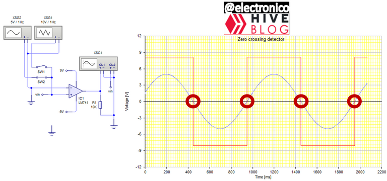
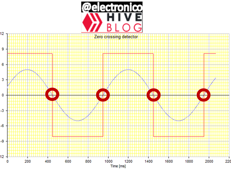
We configure the operational amplifier so that it produces a change in its output when the measured signal crosses the level of 0 which can occur in two directions, from a positive value to a negative value and from a negative value to a positive value.
When the change is from positive to negative the output goes from positive saturation to negative saturation and when the change is from negative to positive the output goes from negative saturation to positive saturation, the change in the output occurs just at the moment when the signal is zero, that is why we call it a zero crossing detector.
El principio de operación es muy sencillo, lo que hacemos es generar una señal controlada cuya función dependerá del comportamiento de una señal no controlada.
Configuramos el amplificador operacional de manera que produzca un cambio en su salida cuando la señal medida cruce el nivel de 0 lo cual puede ocurrir en dos sentidos, de un valor positivo a un valor negativo y de un valor negativo a un valor positivo.
Cuando el cambio es de positivo a negativo la salida pasa de saturación positiva a saturación negativa y cuando el cambio es de negativo a positivo la salida pasa de saturación negativa a saturación positiva, el cambio en la salida ocurre justo en el momento en el que la señal es cero, por eso lo llamamos detector de cruces por cero.
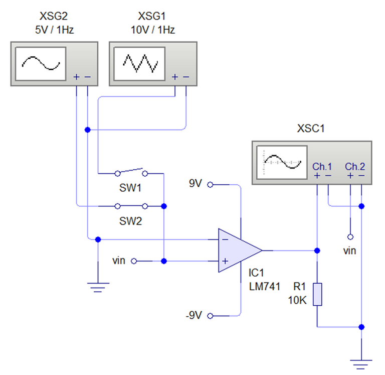
The circuit design is also simple, for this we will use an open loop operational amplifier so that it acts as a comparator, if we place a fixed value at the inverting input then the value of a variable signal at the non-inverting input will produce a change in the output when there is a change for values equal to that of the inverting input.
When V(+)>V(-) then out goes from -Vsat to +Vsat and vice versa, as we want these changes to occur at zero crossings the fixed value we place on the inverting input is 0V, this is achieved by connecting this input to ground.
El diseño del circuito también es simple, para ello usaremos un amplificador operacional en lazo abierto de manera que actúa como un comparador, si colocamos un valor fijo en la entrada inversora entonces el valor de una señal variable en la entrada no inversora producirá un cambio en la salida cuando exista un cambio para valores iguales al de la entrada inversora.
Cuando V(+)>V(-) entonces out pasa de -Vsat a +Vsat y viceversa, como queremos que estos cambios se produzcan en los cruces por cero el valor fijo que colocamos en la entrada inversora es 0V, esto se logra conectando esta entrada a tierra.
Previously we used the comparator circuit to sense the small changes that may occur in a variable and thus create a discrete control, this time we are applying the same principle to a periodic signal, that is, it will be constantly changing its values even at a very fast rate.
Now the interesting question arises: Why on earth should I care when a signal crosses zero if it is doing so at a rate of 30 times per second?
Circuits are designed to meet needs and needs arise when we work on specific applications, now let's think about an ideal charge transfer system.
A load transfer system consists of a main and an auxiliary power supply. When the main supply fails, the load is instantly transferred to the auxiliary and no power outages occur.
When the main supply is restored the auxiliary source has to return the load but here an important phenomenon occurs, to transfer the load it must be guaranteed that both sine waves are in phase so that in this way the load does not suffer possible damage.
Anteriormente usamos el circuito comparador para sensar los pequeños cambios que puedan ocurrir en una variable y de esta forma crear un control discreto, en esta ocasión estamos aplicando el mismo principio a una señal periódica, es decir, estará cambiando constantemente sus valore incluso a un ritmo muy rápido.
Ahora se produce la pregunta interesante: ¿Por qué rayos debería interesarme cuando una señal cruza por cero si lo está haciendo a un ritmo de 30 veces por segundo?
Los circuitos se diseñan para satisfacer necesidades y las necesidades surgen cuando trabajamos en aplicaciones específicas, ahora pensemos en un sistema de transferencia de cargas ideal.
Un sistema de transferencia de cargas consiste en un suministro de energía principal y uno auxiliar, cuando falla el suministro principal la carga se transfiere instantáneamente al auxiliar y no ocurren cortes de energía.
Cuando se restablece el suministro principal la fuente auxiliar tiene que devolverle la carga pero aquí ocurre un fenómeno importante, para transferir la carga se debe garantizar que ambas ondas senoidales estén en fase para que de esta forma la carga no sufra posibles daños.
In order to transfer the load the phases must be synchronized and a zero cross detector is very useful in this task, we can control the phase of the auxiliary supply but not the main supply, then we detect the zero crossings of the main supply and vary the phase of the auxiliary until the zero crossings coincide in the same direction.
So the main utility of a zero crossing detector is in synchronization applications and it is important to note that regardless of the shape of the input waveform the output will still respond to the zero crossings so it applies not only to sine waves but to anything that oscillates between values greater and less than zero.
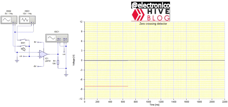
As usual I offer an illustrative simulation of the above.
Para poder transferir la carga las fases se deben sincronizar y un detector de cruces por cero es muy útil en esta tarea, podemos controlar la fase del suministro auxiliar pero no el del suministro principal, entonces detectamos los cruces por cero del suministro principal y variamos la fase del auxiliar hasta que los cruces por cero coinciden en la misma dirección.
Así que la utilidad principal de un detector de cruces por cero es en aplicaciones de sincronización y es importante resaltar que sin importar la forma que tenga la onda de entrada la salida seguirá respondiendo a los cruces por cero por lo que no solo se aplica a ondas senoidales sino a cualquiera que oscile entre valores mayores y menores que cero.
Como de costumbre les ofrezco una simulación ilustrativa de lo dicho.


Thanks for your contribution to the STEMsocial community. Feel free to join us on discord to get to know the rest of us!
Please consider delegating to the @stemsocial account (85% of the curation rewards are returned).
Thanks for including @stemsocial as a beneficiary, which gives you stronger support.