TMR2: Closing the timers cycle EN/ES
If we consider that the advantages of TMR1 over TMR0 come because it is a 16-bit timer versus an 8-bit timer there would be no need to present TMR2 which is also 8-bit, however, in this article we will learn the importance of each of the timers and finish with a circuit for TMR2 after having described its theoretical foundations.
El tema de los temporizadores nos ha ocupado ya suficiente contenido y se hace necesario cerrar el ciclo, por eso es importante dejar claro el tema de los temporizadores, especialmente luego de haber "avergonzado" un poco al TMR0 haciendolo competir con el TMR1.
Si consideramos que las ventajas del TMR1 sobre el TMR0 vienen porque es un temporizador de 16bits frente a uno de 8bits no habría necesidad de presentar el TMR2 que también es de 8 bits, sin embargo, en este artículo aprenderemos la importancia de cada uno de los temporizadores y finalizaremos con un circuito para TMR2 luego de haber descrito sus fundamentos teóricos.
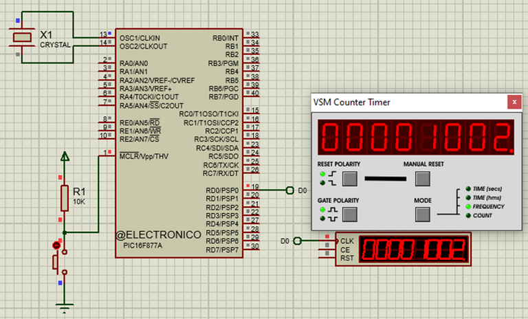
Circuit to simulate application of TMR2. Src: @electronico
Importance of TMR0 |
|---|
Once we have demonstrated the efficiency of TMR1 vs TMR0 we might question why we take time to learn about TMR0 when it seems obvious that in the presence of TMR1 we will never get to choose it.
The indisputable truth is that TMR1 is a better timer available on the same chip, however this is not true for all microprocessors, there are microprocessors that only include TMR0 so being the only option it must be used if or if. Generally these are cheaper chips so when the application does not require much precision we can choose a cheaper chip with TMR0.
And why has it been included in chips where TMR1 is present, I do not have the answer from the manufacturer but I quote my own common sense: the first thing is that it is still a useful resource as a timer and could work in conjunction with TMR1, on the other hand TMR0 has the function of counter which does not apply to TMR1, this is that it can count pulses entering the PIN A4 and even produce overflow interrupts which adds extra utility, so a resource only ceases to be useful when our imagination puts limits 😉.
Una vez que hemos demostrado la eficiencia del TMR1 vs TMR0 pudiesemos cuestionarnos por qué tomamos tiempo para aprender sobre TMR0 cuando parece obvio que en presencia de TMR1 nunca llegaremos a elegirlo.
La verdad indiscutible es que TMR1 es un mejor temporizador disponible en el mismo chip, sin embargo esto no es cierto para todos los microprocesadores, existen microprocesadores que solo incluyen a TMR0 por lo que al ser la única opción debe usarse si o si. Por lo general se trata de chips más económicos así que cuando la aplicación no exige mucha precisión podemos optar por elegir un chip más económico con TMR0.
Y ¿Por qué ha sido incluído en chips donde está presente TMR1?, no tengo la respuesta del fabricante pero cito a mi propio sentido común: lo primero es que sigue siendo un recurso útil como temporizador y podría trabajar en conjunto con TMR1, por otro lado TMR0 tiene la función de contador la cual no aplica para TMR1, esto es que puede contar pulsos que entran por el PIN A4 e incluso producir interrupciónes por desborde lo cual añade utilidad extra, así que un recurso solo deja de ser útil cuando nuestra imaginación le pone límites 😉.
https://images.ecency.com/p/RGgukq5E6HBNvuPpuJoWwfXPpi5ckcLESTB3nmmnKh24McrDqhJBbk29eJg6nhHccsTnRUGy4evvPTbYMyNoAP3a1QZ5UiMYFjCAJ1WED2XgVUZPnUSv88oucBsnfDo.webp?format=webp&mode=fit
Circuit created to simulate the TMR0 in the article TMR0 INTERRUPTION EN/ES. Src: @electronico
Importance of TMR1 |
|---|
TMR1 is a 16bit timer that provides a better accuracy compared to TMR0 and TMR2 in terms of time, it does not mean that its accuracy is useful for all processes regardless of their demands, we must take into account that the microcontrollers we are using are not the most suitable for demanding applications, however I am sure that they can satisfy a large percentage of our creations.
TMR1 instead of an external counter as TMR0, has a module called capture/compare that gives an extra utility apart from keeping time, I have not wanted to touch this module because it requires a little more advanced knowledge and I do not consider that it is the time, but surely in the future we will work with it.
TMR1 es un temporizador de 16bits que brinda una mejor precisión frente a TMR0 y TMR2 en cuanto al tiempo, no significa que su precisión sea útil para todos los procesos sin importar sus exigencias, debemos tomar en cuenta que los microcontroladores que estamos usando no son los más aptos para aplicaciones exigentes, sin embargo estoy seguro que pueden satisfacer un gran porcentaje de nuestras creaciones.
TMR1 en lugar de un contador externo como TMR0, posee un módulo llamado captura/compara que le da una utilidad extra aparte de llevar el tiempo, no he querido tocar este modulo porque requiere conocimientos un poco más avanzados y no considero que sea el momento, pero de seguro en el futuro vamos a trabajar con él.
https://images.ecency.com/p/HNWT6DgoBc1692QWn5trsGLxi44TrGuNZJMEdibAxCR7SCvXCnEiHbm9xERJWS2wnDbqdZWdmN3oyFe7kcEQRdH4kZMXRdmsHGdHzvcWRVAc7t5DczYpiGFPc1B.webp?format=webp&mode=fit
Circuit created to simulate the TMR1 in the article TMR1: Time as a critical variable EN/ES. Src: @electronico
Introducing TMR2 |
|---|
Who would have imagined... a third timer appears on the scene! If you thought that this was coming to take the crown to TMR1 I regret to tell you that it is not, it is an 8bit timer so it can hardly beat TMR1, at least in terms of resolution.
In fact although we can make times with TMR2 this one was not even thought to try it, TMR2 makes times with another purpose: To generate signals.
We define and will use TMR2 as a signal generator, specifically a square wave signal, what we will do is to define the frequency of that signal using TMR2 and we will also take advantage that we can modify this wave to generate PWM signals (but not in this article, but in the future).
Quien lo hubiera imaginado... un tercer temporizador aparece en escena!!. Si pensaste que este venía para quitarle la corona al TMR1 lamento decirte que no es así, se trata de un temporizador de 8bits por lo que difícilmente pueda superar a TMR1, al menos en términos de resolución.
De hecho aunque podemos hacer tiempos con TMR2 este ni siquiera fue pensado para intentarlo, TMR2 hace tiempos con otro propósito: El de generar señales.
Definimos y usaremos a TMR2 como un generador de señales, específicamente una señal de onda cuadrada, lo que nosotros haremos será definir la frecuencia de esa señal usando TMR2 y también aprovecharemos que podemos modificar esta onda para generar señales PWM (pero no en este artículo sino en el futuro.)
TMR2 features |
|---|
Trying to compare it with the previous ones we will notice that it also has a prescaler that in this case can have a maximum value of 16, and also has a postcaler that can take 3 values between 1, 2 and 3 but to simplify we will always give it the value of 1.
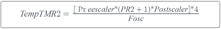
TMR0 and TMR1 count from 0 to the maximum that their bits allow (255 for TMR0 and 65535 for TMR1) and then "overflow" producing the interrupt (if it was enabled), TMR2 increases its count always starting at 0 (we do not charge it values as above) with each statement that is executed and its called value is always compared to a PR2 register, when these values match (the number of times the postscaler defines, that's why we will always use the value 1). The formula to calculate the time that can be done with TMR2 is:
Intentando compararlo con los anteriores notaremos que también tiene un preescaler que en este caso puede tener un valor máximo de 16, y adicionalmente tiene un postcaler que puede tomar 3 valores entre 1, 2 y 3 pero para simplificar siempre le daremos el valor de 1.
TMR0 y TMR1 cuentan desde 0 hasta el máximo que sus bits les permiten (255 para TMR0 y 65535 para TMR1) y luego se "desbordan" produciendose la interrupción (si fue habilitada), TMR2 aumenta su cuenta iniciando siempre en 0 (no le cargamos valores como a los anteriores) con cada instrucción que se ejecuta y su valor siempre se compara con un registro llamado PR2, cuando estos valores coinciden (la cantidad de veces que defina el postscaler, por eso siempre usaremos el valor 1). La fórmula para calcular el tiempo que se puede hacer con TMR2 es:
If we want to calculate the maximum time that we can do with TMR2, we must replace the variables by their maximum possible values; Prescaler = 16, PR2 is an 8Bit register, therefore = 255, Postscaler = 3 and Fosc = 20MHz. In this way we obtain that the maximum time that we can achieve is: 0.0024576 seconds, however, the task of time will be left to TMR1.
Since TMR2 will be used to generate frequencies, what we are interested in calculating is PR2, which we clear from the formula to obtain:
Si deseamos calcular cuanto es el tiempo máximo que podemos hacer con TMR2 debemos reemplazar las variables por sus máximos valores posibles; Preescaler = 16, PR2 es un registro de 8Bits, por lo tanto = 255, Postscaler = 3 y Fosc = 20MHz. De esa forma obtenermos que el tiempo máximo que podemos lograr es de: 0.0024576 segundos, sin embargo la tarea del tiempo se la dejaremos a TMR1.
Dado que TMR2 será usado para generar frecuencias lo que nos interesa calcular es PR2, el cual despejamos de la fórmula para obtener:

However, there are two modifications that we must make to this formula to adapt it to our frequency generator, the first is that our postscaler will always have a value of 1, therefore we can eliminate it from the formula.
The second is that to generate a square wave, two interrupts are needed, one for the rising edge and one for the falling edge, so we must divide the time by 2 if we want to find the correct value to load into PR2 for a given frequency. In this way our definitive formula to generate frequencies would be:
Sin embargo existen dos modificaciones que debemos hacer a esta fórmula para adaptarla a nuestro generador de frecuencia, la primera es que nuestro postscaler siempre tendrá un valor de 1 por lo tanto podemos eliminarlo de la fórmula.
La segunda es que para generar una onda cuadrada se necesitan dos interrupciones, una para el flanco de subida y otra para el flanco de bajada, por lo cual debemos dividir el tiempo entre 2 si queremos encontrar el valor correcto a cargar en el PR2 para una frecuencia dada. De esta manera nuestra fórmula definitiva para generar frecuencias sería:

We know that the fosc is 20MHz (for our case) and that we can set the value we want from those allowed by the prescaler, for which we always take the maximum (16) but we do not know the value of TempTMR2 and we have already said that it cannot be load a value in TMR2 but it always starts its count from 0 and restarts when it matches the value of PR2 (which we can load).
But TempTMR2 is the value of the period associated with the frequency we want to generate and we know that the period T=1/f which makes it easy for us to know the value of TempTMR2 for any frequency we want.
Now we are going to try to generate a frequency of 1KHz, for which we calculate how much T should be when f=1000000hz, which is 1/1000000 seconds. This is 0.001 s or 1ms, if we replace TempTMR2 in the formula by this value we will obtain that for a frequency of 1KHz we must load the value of 155 in PR2.
Sabemos que la fosc es de 20MHz (para nuestro caso) y que podemos el valor que queramos de los permitidos por el preescaler, para lo cual tomamos siempre el máximo (16) pero no conocemos el valor de TempTMR2 y ya digimos que no se puede cargar un valor en TMR2 sino que este comienza su cuenta siempre desde 0 y se reinicia cuando coincide con el valor del PR2 (que si podemos cargar).
Pero TempTMR2 es el valor del período asociado a la frecuencia que deseamos generar y sabemos que el período T=1/f lo cual nos fácilita conocer el valor de TempTMR2 para cualquier frecuencia que deseemos.
Ahora vamos a intentar generar una frecuencia de 1KHz, para lo cual calculamos cuanto debe ser T cuando f=1000000hz que es 1/1000000 segundos. Esto es 0.001 s o 1ms, si reemplazamos TempTMR2 en la fórmula por este valor obtendremos que para una frecuencia de 1KHz debemos cargar en PR2 el valor de 155.
Programming |
|---|
The program is one of the simplest we have created, it consists of causing the interruption by TMR2 and changing the state of an output PIN in the microcontroller so that it is the one that generates the pulses, two interruptions are needed to generate a period (one for the high edge and one for the low edge). The PIN that I have chosen is D0, so we activate port D and the line to adjust our TMR2 is setup_timer_2(T2_DIV_BY_PREESCALER, PR2, POSTCALER); where we must replace the three values that we chose in prescaler (16), PR2 (155) and Postscaler (1). Output activation and deactivation is written to the interrupt macro.
El programa es de los más sencillos que hemos creado, consiste en provocar la interrupción por TMR2 y cambiar de estado un PIN de salida en el microcontrolador para que sea este quien genere los pulsos, se necesitan dos interrupciones para generar un período (uno para el flanco alto y otro para el flanco bajo). El PIN que he elegido es D0 por lo que activamos el puerto D y la línea para ajustar nuestro TMR2 es setup_timer_2(T2_DIV_BY_PREESCALER, PR2, POSTCALER); donde debemos reemplazar los tres valores que elegimos en preescaler (16), PR2 (155) y Postscaler (1). La activación y desactivación de salida se escribe en el macro de la interrupción.
#include <16f877a.h>

#fuses HS,NOWDT,NOPROTECT,NOPUT,NOLVP,BROWNOUT

#use delay(clock=20M)

#use standard_io(D)

#INT_TIMER2

void timer2_interrupcion()

{

   output_toggle(PIN_D0);

}

void main()

{

   setup_timer_2(T2_DIV_BY_16, 155, 1);

   enable_interrupts(INT_TIMER2);

   enable_interrupts(GLOBAL);

   output_low(PIN_D0);

   while(true)

   {

   }

}
SIMULATION |
|---|
For our simulation we will connect a frequency meter to PIN D0 which is where our 1KHz signal will be generated and when activating our circuit it should measure a frequency very close to this value (remember that errors are always present).
Para nuestra simulación conectaremos un medidor de frecuencias en el PIN D0 que es donde se generará nuestra señal de 1KHz y al activar nuestro circuito debería medir una frecuencia muy cercana a este valor (recordemos que los errores siempre están presentes).


¡Enhorabuena!
✅ Has hecho un buen trabajo, por lo cual tu publicación ha sido valorada y ha recibido el apoyo de parte de CHESS BROTHERS ♔ 💪
♟ Te invitamos a usar nuestra etiqueta #chessbrothers y a que aprendas más sobre nosotros.
♟♟ También puedes contactarnos en nuestro servidor de Discord y promocionar allí tus publicaciones.
♟♟♟ Considera unirte a nuestro trail de curación para que trabajemos en equipo y recibas recompensas automáticamente.
♞♟ Echa un vistazo a nuestra cuenta @chessbrotherspro para que te informes sobre el proceso de curación llevado a diario por nuestro equipo.
🥇 Si quieres obtener ganancias con tu delegacion de HP y apoyar a nuestro proyecto, te invitamos a unirte al plan Master Investor. Aquí puedes aprender cómo hacerlo.
Cordialmente
El equipo de CHESS BROTHERS
Muchas gracias por valorar mi contenido y apoyar.!!!
Thanks for your contribution to the STEMsocial community. Feel free to join us on discord to get to know the rest of us!
Please consider delegating to the @stemsocial account (85% of the curation rewards are returned).
You may also include @stemsocial as a beneficiary of the rewards of this post to get a stronger support.