Making an Ohmmeter EN/ES
Ready to join me in designing a very useful tool in electronics?
Good! I think we have seen enough material to allow us to create an Ohmmeter and that is what we will see in this article, for this we will use a PIC18F4550 microcontroller communicating with an OLED display via I2C and our sensor will be an ADC measuring a voltage divider.
Join me for the details.
¿Listos para acompañarme en el diseño de una herramienta muy útil en la electrónica?
¡Bien! Creo que hemos visto suficiente material como para permitirnos el crear un Ohmímetro y es lo que veremos en este artículo, para ello usaremos un microcontrolador PIC18F4550 comunicándose con una pantalla OLED mediante I2C y nuestro sensor será un ADC midiendo un divisor de voltaje.
Acompáñame para los detalles.
Operating philosophy |
|---|
With everything we already know we are able to make our own ohmmeter so... wait.... What is an ohmmeter?
In a nutshell an ohmmeter is a measuring instrument that we can use to know the values of electrical resistances measured in ohms, considering that all electronic circuits have resistors we can already get an idea of how useful it can be.
The fundamental parts that an ohmmeter must have are: The terminals of connection to the resistance to be measured, the transducers that are in charge of converting and interpreting the value of the variable in ohms and an analog or digital indicator by means of which the results can be shown.
Con todo lo que ya sabemos estamos en la capacidad para hacer nuestro propio ohmímetro así que... espera... ¿Qué es un ohmímetro?
En resumidas palabras un ohmímetro es un instrumento de medición que podemos utilizar para conocer los valores de las resistencias eléctricas medidas en ohmios, considerando que todos los circuitos electrónicos poseen resistencias ya podemos hacernos una idea de lo útil que puede ser.
Las partes fundamentales que debe tener un ohmímetro son: Los terminales de conexión a la resistencia que se desea medir, los transductores que se encargan de convertir e interpretar el valor de la variable en ohmios y un indicador analogico o digital mediante el cual se puedan mostrar los resultados.

Our indicator will be an OLED display, so we can say that our ohmmeter is digital, now let's pay a little attention to the way we will design our transducer.
We will use the voltage divider principle and by means of it we will take the output voltage as a reference to know the value in ohms of the resistance we are measuring, the microcontroller will receive this variable by an ADC input and will be in charge of making the calculations by means of the program we will make for it, then it will show them on the OLED panel.
I consider that at this point it is necessary to see a quick review of what a voltage divider is.
Nuestro indicador será una pantalla OLED, así que podemos decir que nuestro ohmímetro es digital, ahora vamos a prestar un poco de atención en la forma como diseñaremos nuestro transductor.
Usaremos el principio de divisor de tensión y mediante el mismo tomaremos el voltaje de salida como referencia para conocer el valor en ohmios de la resistencia que estamos midiendo, el microcontrolador recibirá esta variable por una entrada ADC y se encargará de realizar los cálculos mediante el programa que haremos para él, luego los mostrará en el panel OLED.
Considero que en este punto se hace necesario ver un repaso rápido de lo que es un divisor de voltaje.
Voltage Divider |
|---|
When we have two or more resistors in series connected to a certain voltage each of them will produce a voltage drop, this individual drop of each resistor will depend in percentage value of the ratio between the ohmic values of the resistors involved. The sum of all the drops should result in the total value of the source voltage.
Now let's take a sample with only two resistors in series connected to a voltage source, in this case we will call the source voltage vi, the resistors will be R1 the one with the end connected to the source and R2 the one with the end connected to ground, the Voltage on resistor R2 could be considered as the output voltage and we will call it vo.
Next we are going to see an image that illustrates what we have said together with the equation that relates each variable.
Cuando tenemos dos o más resistencias en serie conectadas a cierto voltaje cada una de ellas producirá una caída de voltaje, esta caída individual de cada resistor dependerá en valor porcentual de la relacion entre los valores óhmicos de las resistencias involucradas. La suma de todas las caídas debe dar como resultado el valor total del voltaje de fuente.
Ahora tomemos una muestra con sólo dos resistencias en serie conectadas a una fuente de voltaje, en este caso vamos a llamar al voltaje de la fuente vi, las resistencias serán R1 la que tiene el extremo conectado a la fuente y R2 la que tiene el extremo conectado a tierra, el Voltaje en la resistencia R2 podría considerarse como el voltaje de salida y lo llamaremos vo.
A continuación vamos a ver una imagen que nos ilustra lo planteado junto a la ecuación que relaciona cada variable.


If we can clear R1 from the equation to know a given value for known values of vi, vo and R2 then we can use this same circuit as a sensor for the resistors we want to measure since they will substitute R1 in the circuit.
From the above formula we obtain the following formula with which we can calculate the value of R1:
Si podemos despejar R1 de la ecuación para conocer un valor dado para valores conocidos de vi, vo y R2 entonces podemos usar este mismo circuito como sensor para las resistencias que queramos medir ya que éstas sustituirán a R1 en el circuito
De la fórmula anterior obtenemos la siguiente con la cual podemos calcular el valor de R1:

Well, here's some air.... 1... 2... 3... now let's move on.
We know that we can use the ADC of the microcontroller to measure a voltage that can have a maximum range of 0 to 5V (more than that would damage the microcontroller) so for convenience we assume a fixed value for vi of 5V.
We can also assume a value for R2, we will use 5K arbitrarily, although very high or very low values of R2 may affect the sensitivity of the measurement.
Now let's go back to the first performance to calculate vo, as vi and R2 will be fixed values the variations in vo will only be affected by the variations in R1, so for a point value measured at vo through the ADC we can use the second equation and find the value of R1 for that instant of time.
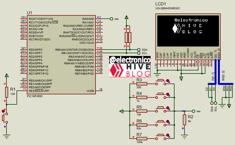
That way we would have our transducer. In the following image we will see it and next to it I have connected test resistors, these resistors replace R1 for different values and the connections are made by pushbuttons for testing purposes in the simulation. We can notice that the connection terminals are the 5V source and the ADC input.
Bueno, toma un poco de aire.... 1... 2... 3... ahora sigamos.
Sabemos que podemos usar el ADC del microcontrolador para medir un voltaje que puede tener un rango máximo de 0 a 5V (más que eso dañaría el microcontrolador) así que por conveniencia asumimos un valor fijo para vi de 5V.
También podemos asumir un valor para R2, usaremos 5K de forma arbitraria, aunque valores muy altos o muy bajos de R2 pueden afectar la sensibilidad de la medición.
Ahora volvamos a la primera actuación para calcular vo, como vi y R2 serán valores fijos las variaciones en vo solo serán afectadas por las variaciones en R1, así que para un valor puntual medido en vo a través del ADC podemos usar la segunda ecuación y encontrar el valor de R1 para ese instante de tiempo.
De esa forma tendríamos nuestro transductor. En la siguiente imagen lo veremos y junto a él he conectado resistencias de prueba, estas resistencias sustituyen a R1 para diferentes valores y las conexiones las hacemos mediante pulsadores para efectos de prueba en la simulación. Podemos notar que los terminales de conexión son la fuente de 5V y la entrada del ADC.

Programming |
|---|
Now all rummaging in the neurons of our microcontroller to make it do what we want 😅.
The first lines in addition to the definition of variables, are of usual configuration explained in previous articles and of course, can not miss some advertising. I share them below.
Ahora toda hurgar en las neuronas de nuestro microcontrolador para que haga lo que queramos 😅.
Las primeras líneas además de la definición de variables, son de configuración habitual explicadas en artículos anteriores y por supuesto, no puede faltar algo de publicidad. Las comparto a continuación.
#include <18f4550.h>

#device ADC = 10

#device PASS_STRINGS = IN_RAM

#fuses HS,NOWDT,NOPROTECT,NOLVP,PUT,CPUDIV1,NODEBUG,VREGEN,NOPBADEN

#use delay(clock=20M)

#use I2C(MASTER, SDA=PIN_B0, SCL=PIN_B1, FAST=400000, STREAM=SSD1306_STREAM)

#define SSD1306_I2C_ADDRESS 0x7A

#include <SSD1306_OLED.c

#include <map_function.c

char valueraw[10];

char vo_value[10];

char res_value[10];

float raw_value;

float r2=5000;

float r1=0;

float vi=5;

float vo;

void main()

{

   setup_adc_ports(AN0);

   setup_adc(adc_clock_internal);

   SSD1306_Begin(SSD1306_SWITCHCAPVCC,

   SSD1306_I2C_ADDRESS);

   SSD1306_ClearDisplay();

   SSD1306_Display();

   SSD1306_DrawText(35, 3, "@electronico", 1);

   SSD1306_Display();

   SSD1306_FillTriangle(30, 25, 35, 15, 40, 25);

   SSD1306_Display();

   SSD1306_FillTriangle(30, 26, 35, 36, 40, 26);

   SSD1306_Display();

   SSD1306_DrawLine(39, 15, 43, 23);

   SSD1306_Display();

   SSD1306_DrawLine(43, 15, 48, 25);

   SSD1306_Display();

   SSD1306_DrawLine(39, 36, 43, 26);

   SSD1306_Display();

   SSD1306_DrawLine(43, 36, 48, 25);

   SSD1306_Display();

   SSD1306_DrawText(52, 16, "H I V E", 1);

   SSD1306_Display();

   SSD1306_DrawText(52, 30, "B L O G ", 1);

   SSD1306_Display();

   Delay_ms(1000);

   SSD1306_ClearDisplay();

   SSD1306_Display();

   SSD1306_DrawText(20, 15, "PRESENTS", 2);

   SSD1306_Display();

   SSD1306_DrawText(13, 37, "Making an Ohmmeter", 1);

   SSD1306_Display();

   Delay_ms(1000);

   SSD1306_ClearDisplay();

   SSD1306_Display();
Now let's go to the neuralgic part of our ohmmeter:
The first thing we want to do is verify that the ADC is reading data correctly, so we take a raw variable and display it on the first line of the OLED panel, remember that because we are using 10 bits the range is 0 to 1023 and that is what we will see in the first sample.
Ahora vamos a la parte neurálgica de nuestro ohmímetro:
Lo primero que queremos hacer es verificar que el ADC está leyendo datos correctamente, así que tomamos una variable cruda y la mostramos en la primera línea del panel OLED, recordemos que por estar usando 10 bits el rango es de 0 a 1023 y eso es lo que veremos en la primera muestra.
while(true)

   {

      set_adc_channel(0);

      delay_us(21);

      raw_value = read_adc();

      SSD1306_DrawRect(0, 0, 128, 15);

      SSD1306_Display();

      sprintf(valueraw, "ADC Value: %f", raw_value);

      SSD1306_DrawText(5, 3, valueraw, 1);

      SSD1306_Display();
That is the value that our microcontroller will receive, we know that vi is 5V so we must adapt a range ratio, for a 0 value of the ADC the voltage vo will be 0V and for the maximum value in the ADC which is 1023 the value of vo will be 5V which is the maximum possible value.
The conversion is done by a rule of 3 and the vo value is displayed on the second line of the OLED panel.
Ese es el valor que recibirá nuestro microcontrolador, nosotros sabemos que vi es 5V asi que debemos adaptar una relacion de rangos, para un valor 0 del ADC el voltaje vo será 0V y para el valor máximo en el ADC que es 1023 el valor de vo será 5V que es el valor máximo posible.
La conversión la hacemos mediante una regla de 3 y la mostramos en pantalla el valor de vo en la segunda línea del panel OLED.
      vo = map(raw_value, 0, 1023, 0, 5);

      sprintf(vo_value, "vo: %f V", vo);

      SSD1306_DrawText(5, 21, vo_value, 1);

      SSD1306_Display();
Finally, to find the value of R1 we apply the second formula given in this article, the microcontroller will receive the values of vo through the ADC and will give the results of the measurement since vi and R2 are known fixed values.
These results are displayed on the third line of our OLED panel, in this way we will see 3 variables in real time, ADC, vo and that of the resistor being measured.
Finalmente, para encontrar el valor de R1 aplicamos la segunda fórmula dada en este artículo, el microcontrolador recibirá los valores de vo a través del ADC y dará los resultados de la medición ya que vi y R2 son valores fijos conocidos.
Estos resultados los mostramos en la tercera línea de nuestro panel OLED, de esta forma veremos 3 variables en tiempo real, ADC, vo y el de la resistencia que se está midiendo.
      r1=(vi-vo)*(r2/vo);

      sprintf(res_value, "RES: %f" , r1);

      SSD1306_DrawText(5, 41, res_value, 1);

      SSD1306_Display();

      delay_ms(100);

   }

}
Simulation |
|---|
Well it's done, now we just have to test it by a small simulation in Proteus, for this I will connect different values of resistors using pushbuttons and compare these values with those shown on the screen.
Remember that due to the resolution of the ADC is possible a small margin of error so it would not be surprising that the measured value differs from the actual value in a small amount (usually negligible or unimportant).
Bueno ya esta hecho, ahora solo tenemos que probarlo mediante una pequeña simulación en Proteus, para ello voy a conectar distintos valores de resistencias mediante pulsadores y compararemos estos valores con los mostrados en pantalla.
Recordemos que debido a la resolución del ADC es posible un pequeño margen de error así que no sería de extrañar que el valor medido difiere del valor real en una pequeña cantidad (generalmente despreciable o sin importancia).

⚠ WARNING ⚠ |
|---|
The ohmmeter designed here is a simple version focused on demonstrating the principle of operation and philosophy of the same in order to encourage learning and creativity of readers with little or no experience in the field. If the reader decides to build the proposed design should take into account the following considerations:
It will be 100% functional as long as the resistors being measured are not connected to any electrical circuit or power source.
This design does not have filters so it is susceptible to noise, to improve it you should add filters that attenuate them, this is not so important if we are only measuring de-energized resistors but it is advisable.
El ohmímetro aquí diseñado es una versión simple enfocada a demostrar el principio de funcionamiento y filosofía de los mismos con la finalidad de incentivar el aprendizaje y la creatividad de lectores con poca o ninguna experiencia en la rama. Si el lector decide construir el diseño planteado debe tomar en cuenta las siguientes consideraciones:
Será 100% funcional siempre y cuando las resistencias que se estén midiendo no estén conectadas a ningún circuito eléctrico o alguna fuente de energía.
Este diseño no posee filtros por lo que es susceptible a ruido, para mejorarlo se deben añadir filtros que los atenúen, esto no es tan primordial si solo estamos midiendo resistencias desenergizadas pero es recomendable.
Se deben implementar circuitos de protección para evitar daños al equipo o personal que le de uso indebido conectándolo a tarjetas energizadas u otras prácticas inseguras que pueden terminar en un evento no deseado.

Yay! 🤗
Your content has been boosted with Ecency Points, by @electronico.
Use Ecency daily to boost your growth on platform!
Support Ecency
Vote for new Proposal
Delegate HP and earn more
Thanks for your contribution to the STEMsocial community. Feel free to join us on discord to get to know the rest of us!
Please consider delegating to the @stemsocial account (85% of the curation rewards are returned).
Thanks for including @stemsocial as a beneficiary, which gives you stronger support.