Control and monitoring: Programming Local control EN/ES
After having created the body (circuit) of our project it's time to bring it to life, I said I would try to have it ready for yesterday but it gave more fight than I expected so between logics and debugging it took me almost all day (a weekend without outings).
Since it was not easy at all you will notice the complexity of what is coming and although we will apply again the pie theory this time it can only help if you have read the 2 previous articles and many of the ones I have written in my blog to present the basics of the techniques and resources that will be used, unless you are an expert in electronics and programming of course.
But don't worry, as usual I will try to be as simple as possible and even if I don't succeed in it we will still have the comments section as a tool to clarify doubts 😉.
Luego de haber creado el cuerpo (circuito) de nuestro proyecto ha llegado la hora de darle vida, dije que intentaría tenerlo listo para ayer pero dio mas pelea de la que esperaba así que entre las lógicas y depuraciones me llevó casi todo el dia (un fin de semanas sin salidas).
Ya que no fue nada fácil advertirás la complejidad de lo que viene y aunque volveremos a aplicar la teoría del pastel esta vez solo puede ayudar si has leido los 2 artículos anteriores y muchos de los que he escrito en mi blog para presentar las bases de las técnicas y recursos que se usarán, a menos que seas un experto en electronica y programacion por supuesto.
Pero no te preocupes, como de costumbre intentaré ser lo más simple posible y aun si no logro tener éxito en ello nos quedará la sección de comentarios como instrumento para aclarar dudas. 😉
Resources |
|---|
Think about it for a moment, we are talking about a critical system in which a failure would cause great material losses and could even cause human losses.
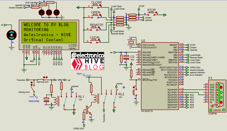
Something like this must be taken very seriously and I have done it, that's why I have designed a system capable of detecting and reporting all possible failures. For the program I have seen the need to use the following resources.
- ADC input to monitor the changes in the variable affected by our control and monitoring system.
- Interruption RB0 to cause a forced stop.
- Interruption RB4-7 for LOCAL, ROMOTE, OPEN, CLOSE pushbuttons.
- USART communication for sending and receiving information to and from an external device (remote mode).
- 20x4 LCD for process monitoring.
- Discrete output management, for activation signal and status indicators.
- Handling of discrete inputs for action pulses and monitoring signals.
- Libraries: 16f877a.h, stdio.h, string.h and LCD_20X4.c.
- And the following variables for data handling:
Piensalo por un momento, hablamos de un sistema crítico en el que una falla causaría grandes pérdidas materiales e incluso pudiese causar pérdidas humanas.
Algo así se debe tomar muy en serio y lo he hecho, por eso he diseñado un sistema capaz de detectar e informar sobre todas las posibles fallas. Para el programa he visto la necesidad de usar los siguientes recursos.
- Entrada ADC para monitorear los cambios en la variable afectada por nuestro sistema de control y monitoreo.
- Interrupción RB0 para provocar una parada forzada.
- Interrupción RB4-7 para pulsadores LOCAL, ROMOTE, OPEN, CLOSE.
- Comunicación USART para enviar y recibir información hacia y desde un dispositivo externo (Modo remoto).
- LCD 20x4 Para monitoreo del proceso.
- Manejo de Salidas Discretas, para señal de activación e indicadores de estado.
- Manejo de entradas discretas para pulsos de acciones y señales de monitoreo.
- Librerías: 16f877a.h, stdio.h, string.h y LCD_20X4.c.
- Y las siguientes variables para el manejo de datos:
char string[20];

char sdv_status[10];

char mode[10];

int estop = 0;

long adc_value;

int c_o_error = 0;

int o_c_error = 0;

int open_signal = 0;

int close_signal = 0;
Control logic |
|---|
The mode variable allows three modes of operation and depending on the mode the system will behave, MODE: STOP sends a closing command to the SDV and blocks the opening and closing controls both locally and remotely, i.e. the SDV cannot be operated (estop=1).
In MODE: LOCAL, it blocks the opening and closing commands from a remote device (PC) and enables the control of the VDS by means of the local OPEN and CLOSE pushbuttons.
In MODE: REMOTE, blocks local open and close commands and enables control from a remote device.
Local and remote control is not allowed simultaneously to avoid two operators taking action in the process without being aware of each other and causing an accident, the only way to choose the operation modes is locally by means of the LOCAL, REMOTE and STOP pushbuttons.
La variable mode permite tres modos de funcionamiento y segun el modo sera el comportamiento del sistema, MODE: STOP envía un comando de cierre a la SDV y bloquea los controles de apertura y cierre tanto local como remoto, es decir, no se puede operar la SDV (estop=1).
En MODE: LOCAL, bloquea los comandos de apertura y cierre desde un dispositivo remoto (PC) y habilita el control de la SDV mediante los pulsadores locales OPEN y CLOSE.
En MODE: REMOTE, bloquea los comandos de apertura y cierre local y habilita el control desde un dispositivo remoto.
No se permite el control local y remoto de forma simultánea para evitar que dos operadores tomen acción en el proceso sin estar conscientes uno del otro pudiendo causar un accidente, la única forma de elegir los modos de operación es de forma local mediante los pulsadores LOCAL, REMOTE y STOP.
The sdv_status variable will display a value depending on the limitswitches opened and closed as well as the open/close signal. The following values are possible:
CLOSED: The limit switch opened is zero and the limit switch closed is 1. This combination is unambiguously interpreted as SDV closed.
C-O TRAN: If the SDV is closed and an open command is received the open_signal will be 1, at the moment the SDV starts opening the limit switch closed opens becoming 0, for a short time before the opening is completed the limit switch opened will also be 0, the combination of these three values implies that the valve is in transition from closed to opened the opened indicator LED will blink to confirm this condition.
These two conditions can be seen in the picture above.
C-O ERR: The SDV lasts a limited and short time between one state and another opened/closed so the transition (state described in the previous paragraph) must be monitored until a certain time, if after the indicated time the transition state is still maintained, an error must occur for the operator to proceed with the necessary attention. In this case C-O ERR indicates that the error occurred when trying to go from Closed to Opened.
La variable sdv_status mostrará un valor que dependerá de los limitswitchs opened y closed además de la señal open/close. Se podrán tener los siguientes valores:
CLOSED: El limit switch opened vale cero y el limit switch closed vale 1. Esta combinación se interpreta inequívocamente como SDV cerrada.
C-O TRAN: Si la SDV está cerrada y se recibe un comando de apertura la señal de apertura (open_signal) será 1, al momento en el que la SDV inicia la apertura el limit switch closed se abre haciéndose 0, por un breve tiempo antes que se complete la apertura el limit switch opened también valdrá 0, la combinación de estos tres valores implica que la válvula está en transición desde closed a opened el LED indicador opened parpadeara para confirmar esta condición.
Estas dos condiciones se pueden apreciar en la imagen anterior.
C-O ERR: La SDV dura un tiempo limitado y corto entre un estado y otro opened/closed por lo que la transición (estado descrito en el párrafo anterior) se debe monitorear hasta cierto tiempo, si luego del tiempo indicado aun se mantiene el estado de transición se debe producir un error para que el operador proceda con la atención necesaria. En este caso C-O ERR indica que el error se produjo cuando se intentaba pasar de Closed a Opened.
OPENED: The limit switch opened is set to 1 and the limit switch close is set to zero, in this condition the SDV is completely open.
O-C TRAN: When the SDV is open and the close command is sent the close_signal variable takes the value 1, this makes the SDV start to close, when moving the value of the limit switch opened will remain at 1 (due to the delay condition that has been implemented in the circuit) and as the close command has been sent the limit switch closed will also be 1, under this condition a transition from OPENED to CLOSED is interpreted.
O-C ERR: When the transition from Opened to Closed has lasted longer than the time necessary for it to be executed, this error is displayed.
OPENED: El limit switch opened vale 1 y el limit switch close vale cero, en esta condición la SDV está completamente abierta.
O-C TRAN: Cuando la SDV está abierta y se envía el comando de cierre la variable close_signal toma el valor 1, esto hace que la SDV comience a cerrarse, al moverse el valor del limit switch opened se mantendrá en 1 (por la condición de retardo que se ha implementado en el circuito) y como se ha enviado el comando close el limit switch closed tambien sera 1, bajo esta condición se interpreta una transición desde OPENED a CLOSED.
O-C ERR: Cuando la transición de Opened a Closed ha durado un tiempo mayor al necesario para que se ejecute se muestra este error.

ERROR: When the limit switch states change without an open or close command being received, this error message will occur.
This error can occur if for some reason in the closed condition the SDV is energized and opens without the command being sent or if in the opened condition power is lost and the SDV closes without a close command being received. Again we will use the switches that allow us to simulate these errors.
Note that the error is different from C-O ERR and O-C ERR even though we are using the same switches because the conditions under which they appear are different.
ERROR: Cuando los estados de los limit switchs cambian sin que se haya recibido un comando de apertura o cierre se producirá este mensaje de error.
Este error puede ocurrir si por alguna razón en el estado closed se energiza la SDV y abre sin que se haya enviado el comando o si en la condición opened se pierde la energía y la SDV se cierra sin haberse recibido un comando de cierre. De nuevo usaremos los interruptores que nos permiten simular estos errores.
Note que el error es distinto a C-O ERR y O-C ERR a pesar de estar usando los mismos interruptores porque las condiciones en que aparecen son distintas.

Unlike control, monitoring must be possible at all times, both in STOP, LOCAL and REMOTE, it must be possible to visualize the value of the variable, system status and SDV status locally through the LCD and LEDs as well as remotely through the PC.
A diferencia del control, el monitoreo debe ser posible en todo momento, tanto en STOP como LOCAL y REMOTE se debe poder visualizar el valor de la variable, estado del sistema y estado de la SDV de forma local a través del LCD y LEDs al igual que de forma remota a través del PC.
Programming |
|---|
Now that we understand the logical operation of our project we are going to represent it in a programming language, the code that we will record in the microcontroller so that it fulfills the described functions.
We begin with the first lines in which we configure the resources to use and declare the variables.
Ahora que ya comprendemos el funcionamiento lógico de nuestro proyecto vamos a representarlo en un lenguaje de programación, el código que grabaremos en el microcontrolador para que cumpla las funciones descritas.
Iniciamos con las primeras líneas en las que configuramos los recursos a usar y declaramos las variables.
#include <16f877a.h>

#device PASS_STRINGS = IN_RAM

#device ADC = 10

#fuses HS,NOWDT,NOPROTECT,NOPUT,NOLVP,BROWNOUT

#use delay(clock=20M)

#use RS232(BAUD=9600, BITS=8, PARITY=N, XMIT=PIN_D1, RCV=PIN_D0, STREAM=PC)

#use fast_io(B)

#use standard_io(C)

#use standard_io(D)

#include <stdio.h

#include <string.h

#define LCD_DB4  PIN_D4

#define LCD_DB5  PIN_D5

#define LCD_DB6  PIN_D6

#define LCD_DB7  PIN_D7

#define LCD_RS   PIN_D2

#define LCD_E    PIN_D3

#include <LCD_20X4.c

char string[20];

char sdv_status[10];

char mode[10];

int estop = 0;

Long adc_value;

int c_o_error = 0;

int o_c_error = 0;

int open_signal = 0;

int close_signal = 0;
We configure the RB0 interrupt for the stop condition, for this we make the estop variable have the value of 1 and we will use it as STOP data in the program, in the same subroutine we send the stop command making 1 the closed_signal variable and turning off the output to the SDV.
Configuramos la interrupción RB0 para la condición de parada, para ello hacemos que la variable estop tenga el valor de 1 y lo usaremos como dato de STOP en el programa, en la misma subrutina enviamos el comando de parada haciendo 1 la variable closed_signal y apagando la salida a la SDV.
#INT_EXT

void interruption_RB0()

{

      estop = 1;

      mode = "STOP";

      output_low(PIN_C0);

      close_signal = 1;

}
We configure the interrupt by RB4-7, the RB4 and RB5 we set the mode variable in LOCAL and REMOTE, as we are changing the working mode these inputs must be able to exit the STOP mode, so we make estop equal to zero.
RB6 and RB7 are open and close commands for the local mode, to avoid that they can be used in a different mode we create the conditional that enables them only when the LOCAL mode is present, the variables open_signal and close_signal are made 1 in each case to start the corresponding operation.
Configuramos la interrupción por RB4-7, el RB4 y RB5 se establece la variable mode en LOCAL y REMOTE, como se esta cambiando el modo de trabajo estas entradas deben ser capaces de salir del modo STOP, por eso hacemos estop igual a cero.
RB6 y RB7 son comandos de apertura y cierre para el modo local, para evitar que puedan ser usados en un modo distinto se crea el condicional que los habilita solo cuando el modo LOCAL está presente, las variables open_signal y close_signal se hacen 1 en cada caso para iniciar la operación correspondiente.
#INT_RB

void interrupcion_RB()

{

   if(input(PIN_B4) == 1)

   {

   mode = "LOCAL";

   estop = 0;

   }

   if(input(PIN_B5) == 1)

   {

   mode = "REMOTE";

   estop = 0;

   }

   if(input(PIN_B6) == 1)

   {

    if(strstr(mode, "LOCAL"))

      {

       open_signal = 1;

      }

   }

   if(input(PIN_B7) == 1)

    if(strstr(mode, "LOCAL"))

      {

       close_signal = 1;

      }

}
Now we move on to the main program and continue with the missing settings for the interrupts, inputs, ADC and LCD, and create the start conditions in STOP mode.
Ahora pasamos al programa principal y continuamos con las configuraciones que faltan para las interrupciones, las entradas, ADC y LCD, además creamos las condiciones de inicio en el modo STOP.
void main()

{

   set_tris_b(0xFF);

   enable_interrupts(INT_EXT);

   ext_int_edge(L_TO_H);

   enable_interrupts(INT_RB);

   enable_interrupts(GLOBAL);

   setup_adc_ports(AN0);

   setup_adc(adc_clock_internal);

   estop=0;

   output_c(0x00);

   mode = "STOP";

   lcd_init();

   lcd_clear();

   delay_ms(100);
Now we show a welcome message, this will be shown only once, for now we will send by USART the same information that we send to the LCD to check that the communication is established, this may change when we set the remote control and monitoring mode.
Ahora mostramos un mensaje de bienvenida, este se mostrara una sola vez, por ahora enviaremos por USART la misma información que enviemos al LCD para comprobar que la comunicación está establecida, esto podra cambiar cuando establezcamos el modo de control y monitoreo remoto.
   lcd_gotoxy(1,1);

   printf(lcd_putc,"WELCOME TO MY BLOG");

   lcd_gotoxy(1,2);

   printf(lcd_putc,"MONITORING");

   lcd_gotoxy(1,3);

   printf(lcd_putc,"@electronico - HIVE");

   lcd_gotoxy(1,4);

   printf(lcd_putc,"Original Content");

   fprintf(PC,"WELCOME TO MY BLOG\r\n");

   fprintf(PC,"MONITORING\r\n");

   fprintf(PC,"@electronico - HIVE\r\n");

   fprintf(PC,"ORIGINAL CONTENT\r\n");

   delay_ms(3000);
Now we will show the message that will be present during the whole execution of the program, for this we include it in a while loop so that the variables are constantly updated.
Ahora mostraremos el mensaje que estará presente durante toda la ejecución del programa, para ello lo incluimos en un bucle while para que se actualicen las variables constantemente.
   while(true)

   {

      lcd_clear();

      adc_value = read_adc();

      lcd_gotoxy(1,1);

      printf(lcd_putc,"CONTROL MODE: %s", mode);

      lcd_gotoxy(1,2);

      printf(lcd_putc,"SDV STATUS: %s", sdv_status);

      lcd_gotoxy(1,3);

      printf(lcd_putc,"ADC VALUE: %Lu", adc_value);

      lcd_gotoxy(1,4);

      printf(lcd_putc,"@electronico - HIVE");

      fprintf(PC,"CONTROL MODE: %s\r\n", mode);

      fprintf(PC,"SDV STATUS: %s\r\n", sdv_status);

      fprintf(PC,"ADC VALUE: %Lu\r\n", adc_value);

      fprintf(PC,"@electronico - HIVE\r\n");

      delay_ms(300);
Now we set the conditions for which the open and close commands will be sent, for this there must not be a forced stop or MODE STOP, in addition the corresponding command must have been received, the variables close_signal and open_signal have been assigned for this purpose because they could be used for both local and remote mode.
We also establish the conditions under which the SDV will indisputably be open or closed based on the information from the limit switches.
Ahora establecemos las condiciones para las cuales se enviaran los comandos de apertura y cierre, para ello no debe haber una parada forzada o MODE STOP, además debe haberse recibido el comando correspondiente, se han asignado las variables close_signal y open_signal para este fin porque se podrían usar tanto para el modo local como para el modo remoto.
También establecemos las condiciones en las que indiscutiblemente la SDV estará abierta o cerrada basándonos en la información de los limit switchs.
       if(open_signal == 1 && estop==0)

         {

         output_high(PIN_C0);

         }

        if(close_signal == 1 && estop==0)

         {

         output_low(PIN_C0);

         }

        if(input(PIN_B1) ==1 && input(PIN_B2) ==0 )

         {

          output_high(PIN_C1);

          output_low(PIN_C2);

          output_low(PIN_C3);

          sdv_status = "CLOSED";

          close_signal = 0;

          o_c_error = 0;

         }

         if(input(PIN_B2) ==1 && input(PIN_B1) ==0)

         {

          output_high(PIN_C2);

          output_low(PIN_C1);

          output_low(PIN_C3);

          sdv_status = "OPENED";

          open_signal = 0;

          c_o_error = 0;

         }
Finally we set the conditions for the transition and error states based on the limit switches and open and close commands as follows:
Finalmente establecemos las condiciones para los estados de transición y error basándonos en los limit switchs y comandos de apertura y cierre como sigue:
        if(input(PIN_B1) ==0 && input(PIN_B2) ==0 )

        {

           if(open_signal ==1 && c_o_error < 10)

            {

             output_toggle(PIN_C2);

             output_low(PIN_C1);

             output_low(PIN_C3);

             sdv_status = "C-O TRAN";

             c_o_error++;

             delay_ms(50);

            }

            if(open_signal ==1 && c_o_error > 9 )

            {

            output_low(PIN_C2);

            output_low(PIN_C1);

            output_high(PIN_C3);

            sdv_status = "C-O ERR";

            }

            if(input(PIN_B1) ==0 && input(PIN_B2) ==0 && open_signal == 0)

            {

            output_low(PIN_C1);

            output_low(PIN_C2);

            output_high(PIN_C3);

            sdv_status = "ERROR";

            }

         }

         if(input(PIN_B1) ==1 && input(PIN_B2) ==1 )

         {

            if(close_signal ==1 && o_c_error < 10)

              {

                output_toggle(PIN_C1);

                output_low(PIN_C2);

                output_low(PIN_C3);

                sdv_status = "O-C TRAN";

                o_c_error++;

                delay_ms(50);

              }

           if(close_signal ==1 && o_c_error > 9 )

              {

               output_low(PIN_C2);

               output_low(PIN_C1);

               output_high(PIN_C3);

               sdv_status = "O-C ERR";

              }

           if(input(PIN_B1) ==1 && input(PIN_B2) ==1 && close_signal == 0)

           {

           output_low(PIN_C1);

           output_low(PIN_C2);

           output_high(PIN_C3);

           sdv_status = "ERROR";

           }

         }
With all this we already have the local mode at 100% and the remote mode at a very advanced level since we only have to establish the signals coming from the remote equipment that will modify the variables open_signal and close_signal, and establish the chain through which we will send the data to be displayed but this is for the next chapter.
For now we can only check through the HERCULES interface that the data are being successfully transmitted via USART between the microcontroller and the PC.
Con todo esto ya tenemos el modo local al 100% y el modo remoto a un nivel muy avanzado ya que solo debemos establecer las señales provenientes del equipo remoto que modificarán las variables open_signal y close_signal, y establecer la cadena mediante la cual enviaremos los datos para ser mostrados pero esto queda para el siguiente capítulo.
Por ahora solo podemos comprobar mediante la interfaz HERCULES que se estan transmitiendo con éxito los datos mediante USART entre el microcontrolador y el PC.
In this way we finish chapter 3 of our series, for the next one which will be the last of this series we are going to create an interface in LabView for remote control from the PC.
I will leave below the links that contain the fundamental information to understand many of the codes and resources used in this article. Thank you for joining me once again and I look forward to your comments.
De esta forma terminamos el capítulo 3 de nuestra serie, para el siguiente que sera la ultima de esta serie vamos a crear una interfaz en LabView para el control remoto desde el PC.
Te dejaré a continuación los enlaces que contienen la información fundamental para comprender muchos de los códigos y recursos usados en este artículo. Agradecido por acompañarme una vez más y quedando atento a tus comentarios.
- Control and monitoring: Circuits EN/ES
- Control and monitoring: Basic fundamentals EN/ES
- USART transmission EN/ES
- RB4-7 Interruptions // Special Edition 💪💪💪 EN/ES
- RB0 INTERRUPT ON PIC16F877A AT HIGH SPEED EN/ES
- Using ADC in PIC16F877a EN/ES
- Manejo de Entradas en un PIC16F877a usando lenguaje C
- Manejo de Salidas en un PIC16F877a usando lenguaje C


Thanks for your contribution to the STEMsocial community. Feel free to join us on discord to get to know the rest of us!
Please consider delegating to the @stemsocial account (85% of the curation rewards are returned).
Thanks for including @stemsocial as a beneficiary, which gives you stronger support.
Congratulations @electronico! You have completed the following achievement on the Hive blockchain And have been rewarded with New badge(s)
Your next target is to reach 30000 upvotes.
You can view your badges on your board and compare yourself to others in the Ranking
If you no longer want to receive notifications, reply to this comment with the word
STOP