Control and monitoring: Basic fundamentals EN/ES
There are moments when while meditating in the silence of my room, fantastic projects and designs come to my mind, then, as if in my mind there was a workshop I enter to organize the ideas, design and develop what I thought, what components to use, what program to use, how to interconnect things until everything begins to operate at 100%.
After it has been created and is operational in the workshop of my mind comes the phase of making it possible in the real world (not that my mind is unreal), in that place where others can see materialized what started in the workshop of my mind.
This is how I have been working for days in the workshop of my mind, trying to carry out an idea that came to visit me, it is to simulate with electronic components a control and monitoring system using only the tools provided by the simulators.
This is a much more complete project to those we are usually used to see in the blog, of course it can also present a higher level of complexity. But don't worry, there is always a way to simplify complex things.
That is why I will present it in several stages, that is, several articles that complement each other but do not overload the reader with a single extensive and complex reading, this is the first of possibly 4 articles, yes, a series, and the best way to start is to establish the basic fundamentals that will facilitate the understanding of subsequent articles.
Hay momentos en los que mientras medito en el silencio de mi habitación vienen a mi mente proyectos y diseños fantásticos, entonces, como si en mi mente hubiera un taller entro a organizar las ideas, diseñar y desarrollar lo pensado, que componentes usar, que programa realizar, como interconectar cosas hasta que todo comienza a operar al 100%.
Luego que ha sido creado y está operativo en el taller de mi mente viene la fase de hacerlo posible en el mundo real (no es que mi mente sea irreal), en ese lugar donde otros pueden ver materializado lo que inició en el taller de mi mente.
Es así como llevo días trabajando en el taller de mi mente, intentando llevar a cabo una idea que vino a visitarme, se trata de simular con componentes electrónicos un sistema de control y monitoreo usando únicamente las herramientas que nos brindan los simuladores.
Este es un proyecto mucho más completo a los que generalmente estamos acostumbrados a ver en el blog, por supuesto también puede presentar un mayor nivel de complejidad. Pero no te preocupes, siempre hay una forma de simplificar las cosas complejas.
Es por eso que lo presentaré en varias etapas, esto es, varios artículos que se complementan entre sí pero que no sobrecargan al lector con una sola lectura extensa y compleja, este es el primero de posiblemente 4 artículos, sí, una serie, y la mejor forma de iniciar es estableciendo los fundamentos básicos que nos faciliten la comprensión de los artículos posteriores.
Previously we have seen some concepts and examples of control and monitoring but this time we will go a little deeper into the subject, for this we will first consider two types of control:
Open loop control: it is when the control action is applied without verifying the result, it is assumed that the action was carried out and the result is always satisfactory, we have done it many times when we send a command to turn on a led, motor or any output from the microcontroller and simultaneously activate an indicator that it is done. The problem with this type of control is that if there is a fault there will be no way for the system to detect it.
Closed loop control: For this case when sending an order to a device, when the order is executed this device returns a signal to the microcontroller indicating that the desired action has been executed, if the activation signal is sent but the activated signal is not received it can be interpreted that there was an error and can proceed to corrections.
Anteriormente hemos visto algunos conceptos y ejemplos de control y monitoreo pero esta vez vamos a ir un poco más profundo en el tema, para ello primeramente vamos a considerar dos tipos de control:
- Control de lazo abierto: Es cuando se aplica la acción de control sin verificar el resultado, se asume que la acción se llevó a cabo y el resultado siempre es satisfactorio, lo hemos hecho muchas veces cuando enviamos un comando para encender un led, motor o cualquier salida desde el microcontrolador y simultáneamente activamos un indicador de que está hecho. El problema con este tipo de control es que si existe una falla no habrá forma de que el sistema la detecte.
- Control de lazo cerrado: Para este caso al enviar una orden a un dispositivo, cuando se ejecuta la orden este dispositivo regresa una señal al microcontrolador indicativa de que se ha ejecutado la acción deseada, si se envía la señal de activación pero no se recibe la señal de activado se puede interpretar que hubo un error y se puede proceder a las correcciones.
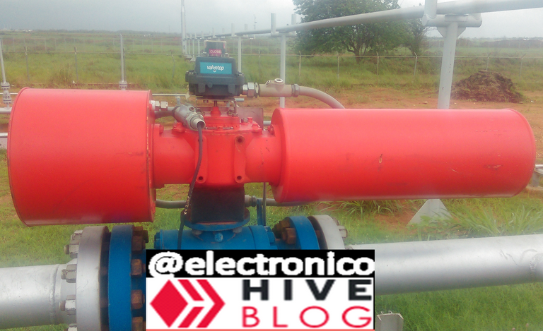
Now let's move on to action, we are in a thermo-electric generation plant in which the fuel for the turbomachines is gas, there is a main pipeline through which all the fuel gas arrives at the plant and then there are the processing stages until it is suitable for consumption by the turbomachines.
From all this we will ignore the turbomachines and gas processing stages and we will focus on the inlet pipeline, if a problem occurs in the plant and we want to stop all processes the correct way would be to cut the main supply and that is only possible if we place a valve in that inlet pipeline.
This valve is usually called SDV, Shut Down Valve and it acts in any emergency to stop the process.
Ahora pasemos a la acción, estamos en una planta de generación termo-eléctrica en la que el combustible de las turbomáquinas es gás, existe un gasoducto principal por el que llega todo el gas combustible a la planta y luego están las etapas de procesamiento hasta hacerlo apto para el consumo de las turbomáquinas.
De todo esto vamos a ignorar a las turbomáquinas y etapas de procesamiento del gas y nos centraremos en el gasoducto de entrada, si ocurre un problema en la planta y queremos detener todos los procesos la forma correcta sería cortando el suministro principal y eso solo es posible si colocamos una válvula en ese gasoducto de entrada.
Esta válvula suele llamarse SDV, Shut Down Valve y actúa ante cualquier emergencia para detener el proceso.
The valve is pneumatic action, this implies that the energy that moves the valve is of this type, it means that there must be a source of compressed air at a certain pressure and the only thing that prevents it from reaching the valve chamber to operate it is a solenoid valve.
The solenoid valve is a valve that operates by means of an electrical signal and through it we can decide when the compressed air will pass to the SDV valve and when it will cut the supply and consequently that signal will serve to carry out the emergency stop.
Now that we are in context let's think about how to design a control and monitoring system for this SDV valve, its actuation is decided by an output signal to the associated solenoid valve.
An operator is 400 meters away from this valve watching the whole process on a PC and from that PC he must see the status of the valve and must be able to send opening and closing commands.
La válvula es de acción neumática, esto implica que la energía que mueve la válvula es de este tipo, significa que debe haber una fuente e aire comprimido a cierta presión y lo único que impide que llegue a la cámara de la válvula para accionarla es una válvula solenoide.
La válvula solenoide es una válvula que acciona por medio de una señal eléctrica y mediante ella podemos decidir cuándo pasará el aire comprimido a la válvula SDV y cuando cortará el suministro y en consecuencia esa señal servirá para llevar a cabo la parada de emergencia.
Ahora que estamos en contexto pensemos en cómo diseñar un sistema de control y monitoreo para esta válvula SDV, su accionamiento se decide por una señal de salida hacia la válvula solenoide asociada.
Un operador está a 400 metros de dicha válvula mirando todo el proceso en un PC y desde ese PC debe ver el estado de la válvula además debe ser capaz de enviarle comandos de apertura y cierre.
Now let's consider which control and monitoring system is the most convenient and how to implement it.
We must take into account that an open/close command starts in the PC commanded by an operator, then the PC will send the command to a PLC (Programing Logic Control) and then the signal will travel through cables up to 400 meters away passing through different junction boxes.
An open loop control system would send the closing command to the SDV and assume that the result will be positive so sending the signal will change the status of the valve on the monitoring screen.
But there could be problems in the PLC, in the wiring to the solenoid valve, the solenoid could be damaged, there could be problems in the compressed air supply and even mechanical failures in the SDV among so many failure factors that could prevent the SVD from actuating.
The operator would be looking on his monitor that the valve closed but if this is not true, gas would still be entering the plant, increasing the pressure in the lines and the risk of a potential catastrophe.
Do you realize how dangerous this can be?
A closed loop control system can be implemented by adding two elements to the valve, these elements are called limit switches and are actuated when the valve is fully open or fully closed. Let's look at the SDV from another angle for a moment.
Ahora vamos a considerar cuál sistema de control y monitoreo es el más conveniente y cómo implementarlo.
Debemos tomar en cuenta que un comando de apertura/cierre inicia en el PC ordenado por un operador, luego el PC enviará el comando a un PLC (Programing Logic Control) y luego la señal viajará por cables hasta 400 metros de distancia pasando por diferentes cajas de conexión.
Un sistema de control a lazo abierto enviaría el comando de cierre a la SDV y asumiría que el resultado será positivo así que al enviar la señal cambiará el estado de la válvula en la pantalla de monitoreo.
Pero pudiese haber problemas en el PLC, en el cableado hasta la válvula solenoide, pudiese estar dañada la solenoide, pudiese haber problemas en el suministro de aire comprimido e incluso fallas mecánicas en la SDV entre tantos factores de fallas que pudiesen impedir que la SVD actúe.
El operador estaría mirando en su monitor que la válvula cerró pero si esto no es cierto seguiría entrando gás a la planta, aumentando la presión en las líneas y el riesgo de una potencial catástrofe.
¿Te das cuenta lo peligroso que puede ser?
Un sistema de control a lazo cerrado se puede implementar añadiendo dos elementos a la válvula, estos elementos se llaman switches de fin de carrera o Limit Switchs y se accionan cuando la válvula está completamente abierta o completamente cerrada. Miremos la SDV desde otro ángulo por un momento.
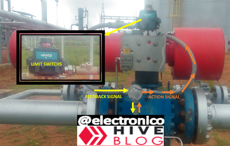
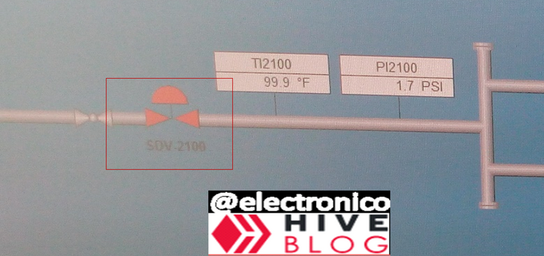
In the image we can see that the electrical conduit is divided into two lines, one that I have marked with orange arrows is the actuation signal, it is the one sent by the operator to actuate the valve.
The other line identified with the yellow arrow contains two return signals, these signals correspond to two switches that are each actuated when the valve has finished its travel in one direction which serves as an indication that it has opened, closed or is in transition, the combination of both signals is interpreted as follows:
If switch A closes when the valve is closed and switch B closes when the valve is open then.
- A=0 and B=0: Power failure, monitoring is not possible.
- A=0 and B=1: Valve open.
- A=1 and B=0: Valve closed.
- A=1 and B=1: Valve in transition (temporary condition).
When a transition is initiated in the valve the system must start a timer and if after a certain time considered sufficient for the execution of the action the state is still in the transition condition it must be interpreted as an error because something obstructs the complete transition.
In this way we could obtain an intrinsically safe control system because even if there are failures in the limit switches the operator will be able to detect it.
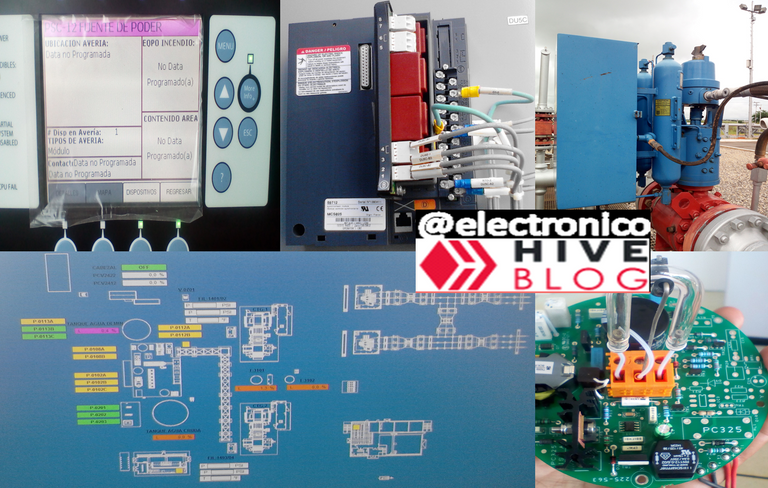
Thus concludes the first installment of this series, all images used are of my authorship, correspond to photos that I have captured during my professional services in some projects. Thank you for your reading. I remain attentive to your comments.
En la imágen podemos notar que la canalización eléctrica se divide en dos líneas, por una que he marcado con flechas naranjas va la señal de accionamiento, es la que envía el operador para accionar la válvula.
La otra línea identificada con la flecha amarilla contiene dos señales de retorno, estas señales corresponden a dos switches que se accionan cada uno cuando la válvula ha terminado su recorrido en una dirección lo cual sirve como indicativo de que ha abierto, ha cerrado o está en transición, la combinación de ambas señales se interpreta como sigue:
Si el interruptor A cierra cuando la válvula está cerrada y el interruptor B se cierra cuando la válvula está abierta entonces.
- A=0 y B=0: Falla en el suministro eléctrico, no es posible el monitoreo.
- A=0 y B=1: Válvula abierta.
- A=1 y B=0: Válvula cerrada.
- A=1 y B=1: Válvula en transición (condición temporal).
Cuando se inicia una transición en la válvula el sistema debe iniciar un temporizador y si luego de cierto tiempo considerado suficiente para la ejecución de la acción el estado sigue en la condición de transición se debe interpretar como un error ya que algo obstruye la transición completa.
De esta forma podríamos obtener un sistema de control intrínsecamente seguro ya que incluso si hay fallas en los limit switches el operador podrá detectarlo.
De esta forma concluye la primera entrega de esta serie, todas las imágenes usadas son de mi autoría, corresponden a fotos que he capturado durante mis servicios profesionales en algunos proyectos. Agradecido por tu lectura Quedo atento a tus comentarios.

Yay! 🤗
Your content has been boosted with Ecency Points, by @electronico.
Use Ecency daily to boost your growth on platform!
Support Ecency
Vote for new Proposal
Delegate HP and earn more
Thank you!!!

Thanks for your contribution to the STEMsocial community. Feel free to join us on discord to get to know the rest of us!
Please consider delegating to the @stemsocial account (85% of the curation rewards are returned).
Thanks for including @stemsocial as a beneficiary, which gives you stronger support.
Thank you!!