Component electronics: Operational amplifier (Close loop) EN/ES
When using an operational amplifier in (open loop) mode we can notice that the gain is so large that the amplifying function is used very little, the high gain is used to detect changes in the inverting and non-inverting inputs at very small voltage levels.
Many instruments work on this principle but this is only one of the applications for operational amplifiers, in fact it is the simplest yet most widely used and effective for the purpose of discrete sensing.
But the very name of the device itself describes its main functions which are to amplify and perform specifically mathematical operations, when we start adding electronic components to the circuit things get more interesting.
Today we are going to add to our knowledge two very simple basic configurations of an operational amplifier working in closed loop, for this we will see how to use the inverting and non-inverting input to amplify for each of them, the difference between the use of each one and the control in the output gain.
Cuando usamos un amplificador operacional en modo (lazo abierto) podemos notar que la ganancia es tan grande que la función de amplificar se usa muy poco, la alta ganancia es aprovechada para detectar cambios en las entradas inversoras y no inversoras a niveles de voltaje muy pequeño.
Muchos instrumentos trabajan bajo este principio pero esta es solo una de las aplicaciones para los amplificadores operacionales, de hecho es la más simple aunque muy usada y eficaz para el propósito de sensores discretos.
Pero el propio nombre del dispositivo describe sus funciones principales las cuales son amplificar y realizar operaciones específicamente matemáticas, cuando comenzamos a añadir componentes electrónicos al circuito las cosas se van poniendo más interesantes.
Hoy vamos a sumar a nuestros conocimientos dos configuraciones básicas muy simples de un amplificador operacional trabajando en lazo cerrado, para ello veremos como usar la entrada inversora y la no inversora para amplificar por cada una de ellas, la diferencia entre el uso de cada una y el control en la ganancia de salida.
Close loop |
|---|
The closed loop consists of applying a feedback at the input, that is, we take a portion of the output signal and make it enter again at the input, by applying this method we obtain a control at the output and it is easy to define a value for the gain based on the external components that are part of the circuit instead of an intrinsic gain of the amplifier.
The operational amplifier is the main reason why I have not stopped to explain amplifier circuits using transistors, if we try with transistors we will get a considerable number of circuits and meshes to obtain the same result that gives us an operational amplifier with very few components.
El lazo cerrado consiste en aplicar una realimentación en la entrada, es decir, tomamos una porción de la señal de salida y la hacemos ingresar nuevamente en la entrada, al aplicar este método se obtiene un control en la salida y es fácil definir un valor para la ganancia basandose los componentes externos que forman parte del circuito en lugar de una ganancia intrínseca del amplificador.
El amplificador operacional es la principal razón de que no me haya detenido a explicar circuitos amplificadores usando transistores, si lo intentamos con transistores obtendremos un número considerable de circuitos y mallas para obtener el mismo resultado que nos brinda un amplificador operacional con muy pocos componentes.
Non-inverting input |
|---|
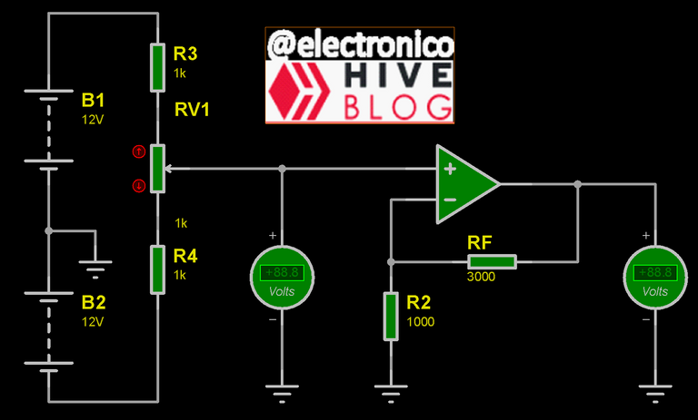
In this case the voltage to be amplified is introduced through the non-inverting input, a feedback is applied through a resistor called RF connected between the output terminal and the inverting input, this resistor together with a second resistor connected between the inverting input and ground allow to adjust the output gain.
En este caso el voltaje que se desea amplificar se introduce por la entrada no inversora, se aplica una realimentación a través de una resistencia llamada RF conectada entre el terminal de salida y la entrada inversora, esta resistencia junto a una segunda resistencia conectada entre la entrada inversora y masa permiten ajustar la ganancia de salida.
In an amplifier the output voltage is the input voltage multiplied by the gain, i.e. the gain determines how much the input voltage has been amplified, we can express it by the following equation:
En un amplificador el voltaje de salida es el voltaje de entrada multiplicado por la ganancia, es decir, la ganancia determina cuánto ha sido amplificado el voltaje de entrada, podemos expresarlo mediante la siguiente ecuación:

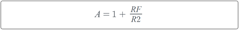
In the case of the non-inverting amplifier the gain A is determined by the following relationship in resistors RF and R2:
En el caso del amplificador no inversor la ganancia A está determinada por la siguiente relación en las resistencias RF y R2:
From this equation we can observe that the gain will always be greater than 1 (There are no negative values for electrical resistors or they would cease to be negative 😉) since the result of the RF/R2 division will always give a number greater than 0 and to this we are going to add 1 we can also say that the gain will always be greater than 1.
Another thing we can notice is that there is no current variable in the equation, these amplifiers have a huge input impedance so the current value is not important but the voltage value, we could use high resistor values and it would not affect the operation, the values that matter are the input voltage and the gain given by the ratio of RF and R2.
We could then calculate a circuit for an accurate output voltage using the following equation:
De esta ecuación podemos observar que la ganancia siempre será mayor que 1 (No existen valores negativos para las resistencias eléctricas o dejarían de serlo 😉) ya que el resultado de la división RF/R2 siempre dará un número mayor que 0 y a este le vamos a sumar 1 podemos decir también que la ganancia siempre será mayor que 1.
Otra cosa que podemos notar es que no existe la variable corriente en la ecuación, estos amplificadores tienen una enorme impedancia de entrada así que el valor de la corriente no es importante sino el de la tensión, podríamos usar valores de resistencias elevados y no afectaría la operación, los valores que importan son el voltaje de entrada y la ganancia dada por la relación de RF y R2.
Podríamos calcular entonces un circuito para un voltaje de salida preciso usando la siguiente ecuación:

Inverting input |
|---|
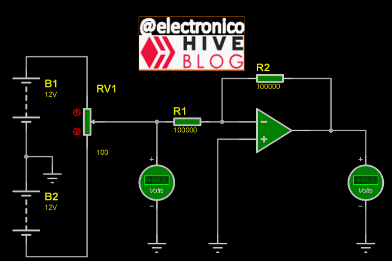
What if we want to use the inverting input? In this case the non-inverting input would have to be connected to ground, again we use an RF between the output and the inverting input and a resistor R1 between the inverting input and the input voltage source. The circuit would look like this:
¿Qué pasaría si deseamos usar la entrada inversora? En este caso la entrada no inversora tendríamos que conectarla a tierra, de nuevo usamos una RF entre la salida y la entrada inversora y un resistencia R1 entre la entrada inversora y la fuente de voltaje de entrada. El circuito tendría el siguiente aspecto:
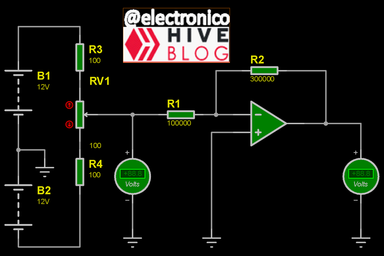
If we can already use the non-inverting amplifier with a very easy to determine gain just by placing values to two resistors it might seem unnecessary to experiment with a second way of amplifying, however although this case seems similar to the previous one, it presents some important variations, again the gain depends on R2/R1 being R2 the feedback resistor but let's detail the A gain equation for this case:
Si ya podemos usar el amplificador no inversor con una ganancia muy fácil de determinar solo colocando valores a dos resistencias podría parecer innecesario experimentar con una segunda forma de amplificar, sin embargo aunque este caso parece similar al anterior, presenta algunas variaciones importantes, de nuevo la ganancia depende de R2/R1 siendo R2 la resistencia de realimentación pero vamos a detallar la ecuación de la ganancia A para este caso:
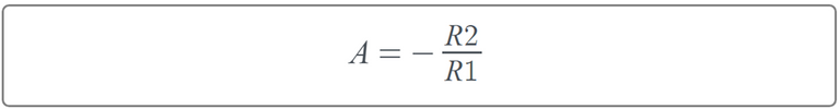
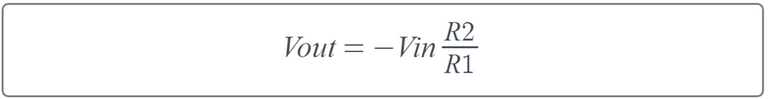
Now we can have gains less than 1 which is usually useful in specific applications where only a percentage value of the input is required at the output, of course it also allows larger gains as long as it does not saturate the amplifier, another important aspect to note is the negative sign that appears in the second member, this implies that the output will be opposite in polarity to the input.
In summary we can have an output signal with a gain greater than 0 which is inverse in polarity to the input signal.
Ahora podemos tener ganancias menores que 1 lo cual suele ser útil en aplicaciones específicas donde solo se requiere en la salida un valor porcentual de la entrada, por supuesto también permite ganancias más grandes siempre y cuando no sature el amplificador, otro aspecto importante a notar es el signo negativo que aparece en el segundo miembro, este implica que la salida será opuesta en polaridad a la entrada.
En resumen podemos tener un señal de salida con una ganancia mayor que 0 que es inversa en polaridad a la señal de entrada.
As a summary we can say that the open loop configuration can be used when you need a sensor can respond to very small voltage variations at the input, this can produce as a response an output voltage up to 12V as allowed by each particular component (defined by datasheet).
But if we want to amplify signals we need to establish a gain control through feedback resistors, in the first case the non-inverting amplifier represents a basic amplifier because we get an output that is equal to the input but of greater magnitude as determined by the gain.
For the inverting amplifier we begin to see another type of utilities in which the output signal depends on the input signal but begins to undergo certain modifications, this principle is used to use capacitors and other components by which the operational amplifiers are used for signal generator circuits, oscillators, filters and many more. But we will go deeper into this later.
For now I appreciate the time you have taken to read and I remain attentive to the comments.
Como resumen podemos decir que la configuración en lazo abierto se puede usar cuando se necesita que un sensor pueda responder a variaciones muy pequeñas de voltaje en la entrada, este puede producir como respuesta un voltaje de salida de hasta 12V según lo permita cada componente en particular (se define por datasheet).
Pero si deseamos amplificar señales necesitamos establecer un control de ganancia mediante unas resistencias de realimentación, en el primer caso el amplificador no inversor representa un amplificador básico ya que se obtiene una salida que es igual a la entrada pero de mayor magnitud según lo determine la ganancia.
Para el amplificador inversor comenzamos a ver otro tipo de utilidades en las que la señal de salida depende de la señal de entrada pero comienza a sufrir ciertas modificaciones, este principio es aprovechado para utilizar condensadores y otros componentes mediante los cuales los amplificadores operacionales son aprovechados para circuitos generadores de señal, osciladores, filtros y muchos más. Pero esto lo profundizaremos más adelante.
Por ahora agradezco el tiempo que te has tomado para leer y quedo atento a los comentarios.


Congratulations @electronico! You have completed the following achievement on the Hive blockchain And have been rewarded with New badge(s)
Your next target is to reach 100 posts.
You can view your badges on your board and compare yourself to others in the Ranking
If you no longer want to receive notifications, reply to this comment with the word
STOPTo support your work, I also upvoted your post!
Check out our last posts:
Thanks for your contribution to the STEMsocial community. Feel free to join us on discord to get to know the rest of us!
Please consider delegating to the @stemsocial account (85% of the curation rewards are returned).
Thanks for including @stemsocial as a beneficiary, which gives you stronger support.
Yay! 🤗
Your content has been boosted with Ecency Points, by @electronico.
Use Ecency daily to boost your growth on platform!
Support Ecency
Vote for new Proposal
Delegate HP and earn more