Component electronics: Digital output expander 74LS164
It is time to add a new component to our list of known components, for its valuable utility and simplicity of understanding I have chosen the 74LS164 component.
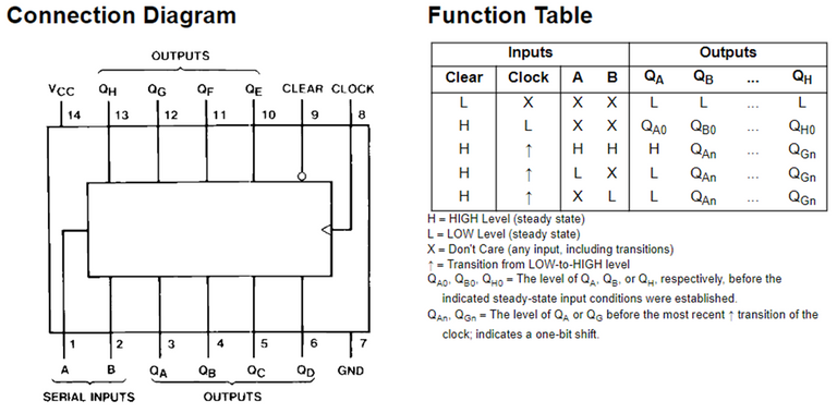
It is a device that has 8 discrete outputs that can be activated or deactivated using only 2 pins of the microcontroller, today we will learn how to use it to expand the outputs of a microcontroller obtaining 6 additional outputs for every 2 of the microcontroller (although the component offers 8 we must subtract from the microcontroller the 2 that we will use to send the data).
Ha llegado el momento de añadir un nuevo componente a nuestra lista de conocidos, por su valiosa utilidad y su simplicidad de comprensión he escogido el componente 74LS164.
Se trata de un dispositivo que posee 8 salidas discretas que pueden ser activadas o desactivadas usando solo 2 pines del microcontrolador, hoy aprenderemos a usarlo para expandir las salidas de un microcontrolador obteniendo 6 salidas adicionales por cada 2 del microcontrolador (aunque el componente ofrece 8 debemos restar del microcontrolador las 2 que usaremos para enviar los datos).
I once looked down on a 12XX series PIC microcontroller because of its few input/output pins available, it is true that in some applications where a demanding program is not necessary it would not be worth wasting resources using an advanced microcontroller but what did not fit me was how the reduction of resources to only 4 input and output pins would really find any application.
I even thought that maybe a relay could have the same performance because we could find relays with more terminals but I was really to discover how we sin for lack of information and sometimes we rush to issue opinions as if we were experts without doing prior research.
What I was missing was the existence of these wonderful input and output expander components that would make a PIC with 6 outputs have 16 in total, this would make possible the design of not so complex projects at very low cost, especially when the need is not the processing power and is required to control a decent number of devices.
Alguna vez llegue a mirar a un microcontrolador PIC de la serie 12XX menospreciándole por sus escasos pines de entrada/salida disponible, es cierto que en algunas aplicaciones en las que no es necesario un programa exigente no valdría la pena malgastar recursos usando un microcontrolador avanzado pero lo que no me cuadraba era como la reducción de recursos a solo 6 pines que debo escoger usar como entrada o salida encontraría realmente alguna aplicación.
Incluso pensaba que tal vez un relé podría tener las mismas prestaciones porque podríamos encontrar reles con más terminales pero realmente estaba por descubrir cómo pecamos por falta de información y a veces nos precipitamos a emitir opiniones como si fuésemos unos expertos sin hacer una investigación previa.
Lo que me faltaba conocer era la existencia de estos maravillosos componentes expansores de entradas y salidas que harían a un PIC de 6 salidas tener 24 en total, esto haría posible el diseño de proyectos no tan complejos a muy bajo costo, especialmente cuando la potencia de procesamiento no es un factor primordial y se requiere controlar un número decente de dispositivos mediante salidas discretas.
alldatasheet
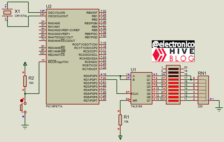
For the microcontroller connections it is similar to the I2C (in terms of connection), one pin is used for the reception of data in serial form from the microcontroller and another one for the clock synchronization.
It is important to highlight that this component only receives the pulse train and reflects them in its output pins, however it does not send any type of communication to the microcontroller, in case you need to verify the data reception automatically you can use one of its outputs as an input to the microcontroller.
Para las conexiones del microcontrolador es algo similar al I2C (En términos de conexión), se usa un pin para la recepción de datos en forma serial desde el microcontrolador y otro para la sincronización de reloj.
Es importante resaltar que este componente solo recibe el tren de pulsos y los refleja en sus pines de salida, sin embargo no envia ningun tipo de comunicación al microcontrolador, en caso de que se necesite verificar la recepción de datos de forma automática se puede usar una de sus salidas como una entrada al microcontrolador.
For our microcontroller to interact with this component there is a library called 74LS164_Pin.h that will make things much easier, in the configuration we only need to define which pin in the microcontroller will be used to send data in serial form and which for the clock data, for this we define them as #define data PIN_NAMEPIN and #define clock PIN_NAMEPIN where obviously NAMEPIN must be replaced by the name of the pin you want to use.
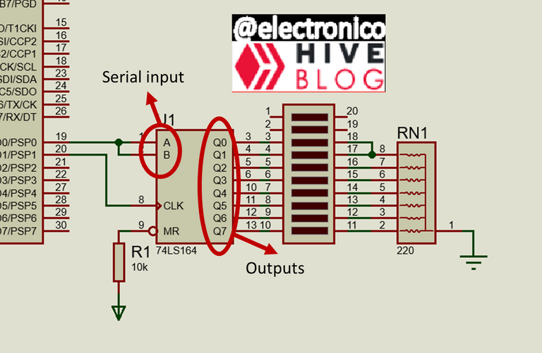
To assign whether the most significant bit is the left or right bit, an 8-bit vector is used as follows: int8 bit_mask[8] = {1,2,4,8,16,32,64,128}; when Q0 is desired to be the most significant and bit_mask[8] = {128,64,32,16,8,8,4,2,1}; when Q7 is desired to be the most significant, this is understood as _bit_mask[8] = {Q7,Q6,Q5,Q4,Q3,Q2,Q1,Q0}; which means that the value we put in Q7 (1 or 128) will be the one it will assume and the other values must follow the binary sequence.
To send data we use the function send_byte_data(DATA, bit_mask); where DATA represents the data we want to transmit, it can have any format but we must take into account that it must be an integer between 0 and 255 that will be converted into 8-bit binary and the result will give the values to each output pin based on the value of the bit that corresponds to that output.
To illustrate this we will see an example in which we will play with a led bar.
Para que nuestro microcontrolador pueda interactuar con este componente existe una librería llamada 74LS164_Pin.h que nos facilitará mucho las cosas, en la configuración solo necesitamos definir qué pin en el microcontrolador será usados para enviar los datos en forma serial y cual para los datos del reloj, para ello los definimos como #define data PIN_NAMEPIN y #define clock PIN_NAMEPIN donde obviamente NAMEPIN debe reemplazarse por el nombre del pin que se desea usar.
Para asignar si el bit más significativo es el de la derecha o la izquierda se usa un vector de 8 bits de la siguiente forma: int8 bit_mask[8] = {1,2,4,8,16,32,64,128}; cuando se desea que Q0 sea el más significativo y bit_mask[8] = {128,64,32,16,8,4,2,1}; cuando se desea que Q7 sea el más significativo, esto se entiende como bit_mask[8] = {Q7,Q6,Q5,Q4,Q3,Q2,Q1,Q0}; lo que significa que el valor que pongamos en Q7 (1 o 128) será el que este asumirá y los demás valores deben seguir la secuencia binaria.
Para enviar datos se usa la función send_byte_data(DATA, bit_mask); donde DATA representa el dato que deseamos transmitir, puede tener cualquier formato pero debemos tomar en cuenta que debe ser un entero entre 0 y 255 que será convertido en binario de 8 bits y el resultado le dará los valores a cada pin de salida basado en el valor que tenga el bit que se corresponda con dicha salida.
Para ilustrar esto vamos a ver un ejemplo en el que jugaremos con una barra de leds.
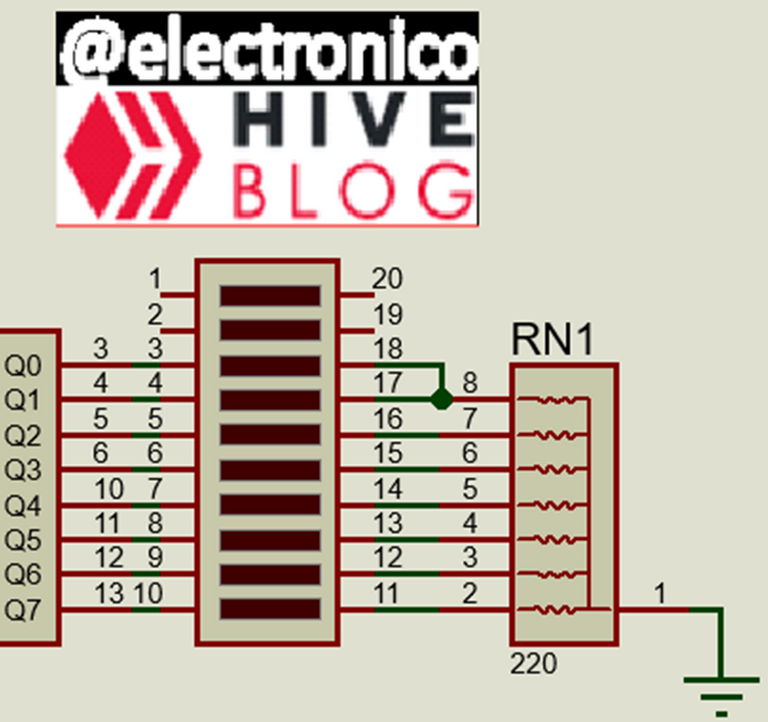
We are going to create a fill/empty effect of the led bar, this implies that the leds will turn on in ascending order and then turn off in descending order in a repetitive way.
To create the ascending animation we must send the data 1 (b000000001), 3(b00000011), 7(b00000111), 15(b00001111), 31(b00011111), 63(b00111111), 127(b01111111) and 255(b1111111111).
If we analyze the values we can notice that after starting at 1 the next one is twice the previous one plus one, which can be expressed as x=2x+1 being this equation the one that determines how x will increase with respect to its previous value to generate the correct sequence (filling effect).
For the descending equation we can use x = (x -1) / 2; to go eliminating the generated values but in reverse direction which will produce the turning off of the leds in a descending way (emptying effect).
We could have sent each value independently but there is no need if we can use mathematics to simplify the path.
In our program x will be a variable called onbar, we will organize the conditions by which the sequences are generated separating them by conditional if and while loops, thanks to the mathematical formulas the program is summarized to very few lines as shown below.
Vamos a crear un efecto de llenado/vaciado de la barra led, esto implica que los leds se encenderán en orden ascendente y luego se apagaran en orden descendente de forma repetitiva.
Para crear la animación ascendente debemos enviar los datos 1 (b000000001), 3(b00000011), 7(b00000111), 15(b00001111), 31(b00011111), 63(b00111111), 127(b01111111) y 255(b11111111).
Si analizamos los valores podemos notar que después de iniciar en 1 el siguiente es dos veces el anterior más uno, lo cual puede expresarse como x=2x+1 siendo esta ecuación la que determina cómo incrementará x respecto a su valor anterior para generar la secuencia correcta (efecto de llenado).
Para la ecuación descendente podemos usar x = (x -1) / 2; para ir eliminando los valores generados pero en sentido inverso lo cual producirá el apagado de los leds en forma descendente (efecto de vaciado).
Pudimos haber enviado cada valor de forma independiente pero no hay necesidad si podemos usar las matemáticas para simplificar el camino.
En nuestro programa x será una variable llamada onbar, organizaremos las condiciones mediante las cuales se generan las secuencias separándolas por condicionales if y bucles while, gracias a las fórmulas matemáticas el programa se resume a muy pocas líneas como se muestra a continuación.
#include <16f877a.h>

#fuses HS,NOWDT,NOPROTECT,NOPUT,NOLVP,BROWNOUT

#use delay(clock=20M)

#use standard_io(D)

#define data PIN_D0

#define clock PIN_D1

#include <74LS164_Pin.h>

int8 bit_mask[8] = {1,2,4,8,16,32,64,128};

int onbar = 1;


void main()

{

   send_byte_init(0x00);

   while(true)

   {

      send_byte_data(onbar, bit_mask);

        if(onbar > 254)

       {

        while(onbar>0)

        {

         send_byte_data(onbar, bit_mask);

         onbar = (onbar -1) / 2;

         delay_ms(50);

        }

       }

      onbar = (onbar *2) + 1;

      delay_ms(50);

   }

}
And the simulation would run as follows:
Y la simulación correría de la siguiente forma:


I did not understand everything I read but the end result is cool.
¿Soy muy malo explicando?
Lo siento... intentaré mejorar!
Gracias por esforzarte en leer todo a pesar de no entender.!!
No. Your not bad at explaining. It is just a bit too technical for me to comprehend.
I had also considered that possibility, in any case I'm glad that the final product was to your liking. Thanks for letting me know.
Yay! 🤗
Your content has been boosted with Ecency Points, by @electronico.
Use Ecency daily to boost your growth on platform!
Support Ecency
Vote for new Proposal
Delegate HP and earn more
Thanks for your contribution to the STEMsocial community. Feel free to join us on discord to get to know the rest of us!
Please consider delegating to the @stemsocial account (85% of the curation rewards are returned).
You may also include @stemsocial as a beneficiary of the rewards of this post to get a stronger support.
Congratulations @electronico! You have completed the following achievement on the Hive blockchain And have been rewarded with New badge(s)
Your next target is to reach 400 replies.
You can view your badges on your board and compare yourself to others in the Ranking
If you no longer want to receive notifications, reply to this comment with the word
STOPCheck out our last posts:
Congratulations your publication has been chosen among the best of the day.
KEEP CREATING GOOD CONTENT.