Ben Eater 6502 Kit — Day 21
The 65C02 has two interrupt lines: NMI (mon maskable interrupt) and IRQ (interrupt request). It should be noted that IRQ are mend to be shared between interrupt sources (devices, I/O chips, etc), while NMI is designed to be used by only one interrupt source.
Mind you “designed for” doesn't mean it's impossible that the NMI is used for multiple interrupt sources. For example on the Atari 800 the NMI was handled by the ANTIC chip which did manage three interrupt sources for the CPU.
Lets connect a button it one of the interrupt pins:
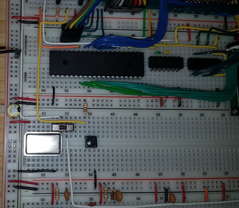
Button connected to IRQ pin
Next we need a program to handle interrupts. Again I made a few changes the source code. Most notable that I use the WAI (wait for interrupt instruction) to reduce power consumption. Also I used BRA (branch always) to jump back to the beginning of the loop and STZ (store zero).
Important: When using the STP or WAI instructions the RDY pin must not be directly connected to 5V. A 3.3kΩ resistor is suggested. That's because the CPU pulls RDY down when the CPU is stopped.
.pc02
.listbytes  16
.pagelength 66
.case     -

.macpack    generic
.include    "VIA.inc"
.include    "LCD.inc"

.segment    "ZEROPAGE"

Counter:    .res 2

.segment    "CODE"
;;
;   RES (reset) handler
;
.proc     Do_RES
    LDX  #$FF
    TXS
    CLI
    STZ  Counter
    STZ  Counter + 1

    VIA_Set_A #%11100000  ; Set top 3 pin as output
    VIA_Set_B #%11111111  ; Set all pins as output

    LCD_Control #%00111000  ; Set 8-bit mode; 2 line display; 5×8 font
    LCD_Control #%00001110  ; Display on; cursor on; blink off
    LCD_Control #%00000110  ; Increment and shift cursor; don't shift display
    LCD_Control #%00000001  ; Clear Display

Loop:     LCD_Control #%00000010  ; Move cursor home
    LCD_Decimal Counter   ; Print number in decimal

    WAI     ; Wait for Interrupt
    BRA  Loop
.endproc

;;
;   NMI (non-maskable interrupt) handler
;
.proc     Do_NMI
    INC  Counter
    BNE  Exit
    INC  Counter + 1
Exit:     RTI
.endproc

;;
;   IRQ (interrupt request) hander
;
.proc     Do_IRQ
    INC  Counter
    BNE  Exit
    INC  Counter + 1
Exit:     RTI
.endproc

.segment    "HEADER"
.word     Do_NMI
.word     Do_RES
.word     Do_IRQ
You might notice that I didn't add the loop to software debounce the switch. I'll come to that latter. For now let's try out the program with the IRQ connected:
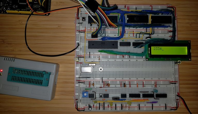
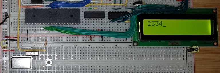
Handling IRQs
As expected one button clock leads to thousands of interrupts. At least when the CPU is attached to the 1MHz clock.
Now, let's try the NMI instead. Do note the 0.1μF capacitor I added to the switch:
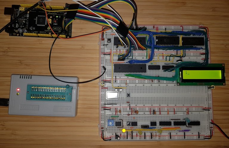
Handling NMIs
As you can see this is enough to debounce the switch. Most of the time. Sometimes one button press might result to two interrupts being triggers.
For this project this is good enough. But if you where to attach a button to say the C64 NMI pins on the user or expansion port then your might want to consider adding a reliable debounce circuit.
You find the source code for the program with makefile, linker configuration file, include files and assembler source code on GitLab: 6502Tutorial — KitInterrupt/NMI.
You find the source code for the program with makefile, linker configuration file, include files and assembler source code on GitLab: 6502Tutorial — Kit/Interrupt/NMI