DETAILED EXPLANATION ON HOW TO MAKE A DIY STOPWATCH USING ARDUINO | OLED | PUSH BUTTON
As it is known that the stopwatch occurs to be a very important device we most of the time use in our daily lives in measuring the time interval of an event. It is highly utilized and stands out due to its high accuracy and precision in which it measures time intervals by the press to a start and stops button. I'm @techlhab and today I would be sharing with us how to make is DIY Smart Stopwatch using an Arduino Uno microcontroller, Push Button, and OLED Display Screen as the major hardware components. While the software components are; the Arduino IDE, Embedded C/C++ programming language, and fritzing for circuit design and simulation.
- Arduino Uno
- OLED Display Screen
- Push Button
- Arduino IDE (Integrated Development Environment)
- Embedded C/C++
- Fritzing
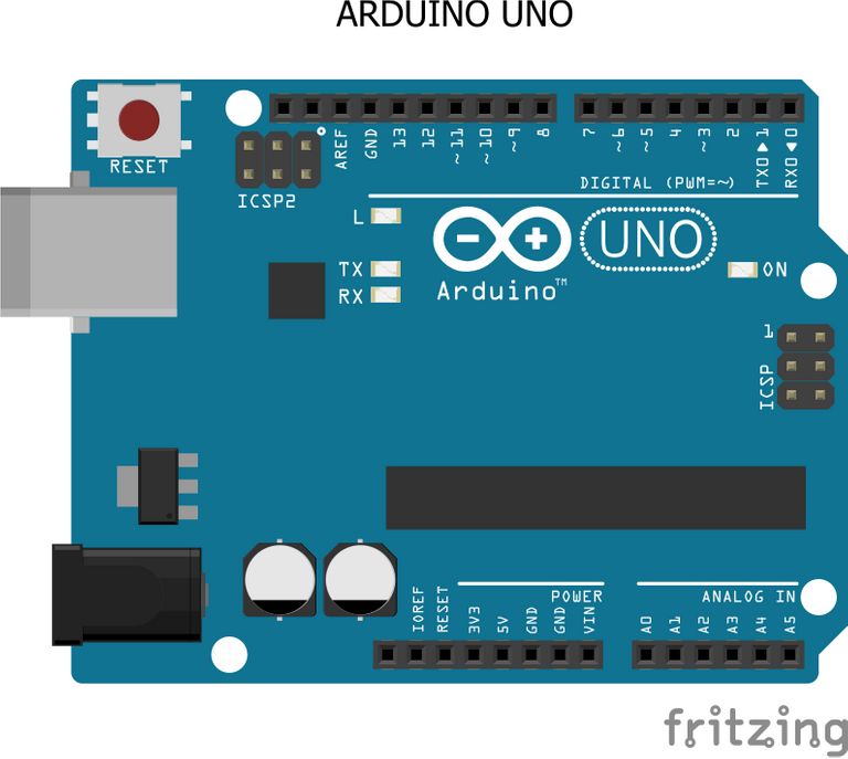
The Arduino Uno is a popular open-source microcontroller that uses the ATMEGA328P PIC (Programmable Integrated Circuit) chip developed by Arduino.cc. It has 14 digital I/O (Input / Output) pins and 6 analog I/O pins.
In this project, that is the stopwatch, the Arduino Uno microcontroller serves as the brain of the device, with which other components connected to it sends and receives instructions to and from respectively based on the code or instructions programmed to the microcontroller.
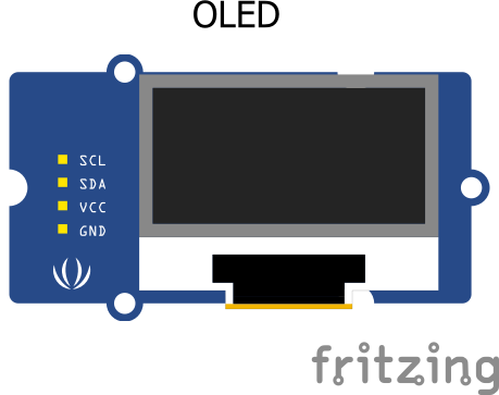
The OLED is a four (4) terminal display screen which helps in displaying relevant information to the users for interactions. And It is used here to serve a major purpose of displaying the stopwatch time as it counts.
It also has 4 pins which are:
- Vcc
- Gnd
- SDA
- SCL
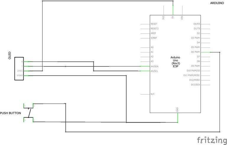
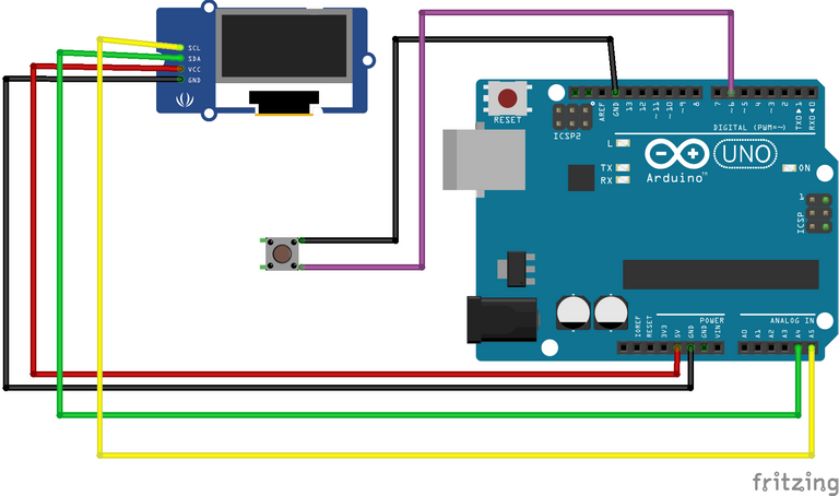
- Conneting the Push Button to the Arduino Uno
| Arduino Uno | Push Button | |
|---|---|---|
| 1 | S | D6 |
| 2 | Gnd | Gnd |
- Conneting the OLED Display Screen to the Arduino Uno
| Arduino Uno | OLED Display Screen | |
|---|---|---|
| 1 | 5v | Vcc |
| 2 | Gnd | Gnd |
| 3 | A4 | SDA |
| 4 | A5 | SCL |
// Arduino OLED Stopwatch

#include <SPI.h>
#include <Wire.h>
#include <Adafruit_GFX.h>
#include <Adafruit_SSD1306.h>
#include <Fonts/FreeSans9pt7b.h>
#include <Fonts/FreeSans18pt7b.h>
#include <Fonts/FreeSans12pt7b.h>

#define SCREEN_WIDTH 128 // OLED display width, in pixels
#define SCREEN_HEIGHT 64 // OLED display height, in pixels

// SCL A5
// SDA A4
#define OLED_RESET 0  // GPIO0
Adafruit_SSD1306 display(SCREEN_WIDTH, SCREEN_HEIGHT, &Wire, OLED_RESET);

#define LOGO_HEIGHT   16
#define LOGO_WIDTH    16


const unsigned char PROGMEM icon [] = {
0x00, 0x1F, 0xF8, 0x00, 0x00, 0x1F, 0xF8, 0x00, 0x00, 0x1F, 0xF8, 0x00, 0x00, 0x1F, 0xF8, 0x00,
0x00, 0x1F, 0xF8, 0x00, 0x00, 0x03, 0xC0, 0x00, 0x00, 0x00, 0x00, 0x40, 0x00, 0x00, 0x00, 0xE0,
0x00, 0x1F, 0xF8, 0xF0, 0x00, 0x7F, 0xFE, 0x70, 0x00, 0xFF, 0xFF, 0x20, 0x01, 0xF0, 0x0F, 0x80,
0x03, 0xC1, 0x83, 0xC0, 0x03, 0x81, 0x81, 0xC0, 0x07, 0x01, 0x80, 0xE0, 0x07, 0x01, 0x80, 0xE0,
0x0E, 0x01, 0x80, 0x70, 0x0E, 0x01, 0x80, 0x70, 0x0E, 0x03, 0xC0, 0x70, 0x0E, 0x03, 0xC0, 0x70,
0x0E, 0x03, 0xC0, 0x70, 0x0E, 0x01, 0x80, 0x70, 0x0E, 0x00, 0x00, 0x70, 0x07, 0x00, 0x00, 0xE0,
0x07, 0x00, 0x00, 0xE0, 0x07, 0x80, 0x01, 0xE0, 0x03, 0xC0, 0x03, 0xC0, 0x01, 0xE0, 0x07, 0x80,
0x00, 0xF8, 0x1F, 0x00, 0x00, 0x7F, 0xFE, 0x00, 0x00, 0x1F, 0xF8, 0x00, 0x00, 0x07, 0xE0, 0x00

};

const unsigned char PROGMEM swatch [] = {
0x03, 0xC0, 0x03, 0xC0, 0x03, 0xC0, 0x00, 0x08, 0x07, 0xEC, 0x0E, 0x70, 0x18, 0x18, 0x30, 0x0C,
0x30, 0x8C, 0x21, 0x84, 0x21, 0x84, 0x30, 0x0C, 0x10, 0x08, 0x18, 0x18, 0x0F, 0xF0, 0x03, 0xC0
};


void setup()   {
  pinMode(6,INPUT_PULLUP);  //Switch
  display.begin(SSD1306_SWITCHCAPVCC, 0x3C);  // initialize with the I2C addr 0x3C (for the 64x48)
  display.display();


  display.clearDisplay();
  display.setFont(&FreeSans9pt7b);
  display.drawPixel(10, 10, SSD1306_WHITE);
  display.setTextColor(WHITE);
  display.setCursor(0,0);
  display.print("Viral Science");
    display.display();
    delay(800);
}
int poz=1;
int broj=1;
int kretanjeY=30;

int sec1=0;
int min1=0;
unsigned long msec=0;
unsigned long mili=0;
int pres=0;
int fase=0;
int start=0;
unsigned long tim=0;
void loop()
  {
      display.clearDisplay();
      if(digitalRead(6)==0)
      {
        if(pres==0)
           {
            fase=fase+1;
            pres=1;
            if(fase>2)
            fase=0;
            }

        }else{pres=0;}

     if(fase==0)
      {
        display.setFont(&FreeSans12pt7b);
        display.setFont();
      display.setCursor(50,50);
      display.print("Start");
      display.drawBitmap(48, 8,  icon, 32, 32, WHITE);


      sec1=0;
      min1=0;
      tim=0;
      mili=0;
      msec=0;
      start=0;
      }

      if(fase==1)
      {
        display.clearDisplay();
        display.setFont(&FreeSans12pt7b);
        display.setFont();
        display.setCursor(37,0);
        display.print("Stopwatch");
        display.setFont(&FreeSans9pt7b);

        if(start==0)
          {
            start=1;
            tim=millis();
          }
       msec=(millis()-tim);


        min1=msec/60000;


        if((msec/1000)>59)
           {
            sec1=(msec/1000)-(min1*60);
            }else{
              sec1=msec/1000;
              }

          mili=(msec%1000)/10;

           display.setCursor(42,30);
           if(min1<=9)
           {
            display.print("0");
            display.print(min1);
            }else {display.print(min1);}

            display.print(":");

             if(sec1<=9)
           {
            display.print("0");
            display.print(sec1);
            }else {display.print(sec1);}
            display.setFont(&FreeSans12pt7b);
            display.setCursor(50,57);

                  if(mili<=9)
           {
            display.print("0");
            display.print(mili);
            }else {display.print(mili);}
       }

if(fase==2)
{
     display.clearDisplay();
     display.setFont(&FreeSans12pt7b);
        display.setFont();
        display.setCursor(52,0);
        display.print("Time:");
        display.setFont(&FreeSans9pt7b);
        display.setCursor(42,30);
           if(min1<=9)
           {
            display.print("0");
            display.print(min1);
            }else {display.print(min1);}

            display.print(":");

             if(sec1<=9)
           {
            display.print("0");
            display.print(sec1);
            }else {display.print(sec1);}
            display.setFont(&FreeSans12pt7b);
            display.setCursor(50,57);

                  if(mili<=9)
           {
            display.print("0");
            display.print(mili);
            }else {display.print(mili);}
             display.drawBitmap(105, 20,  swatch, 16, 16, 1);
             display.drawBitmap(12, 20,  swatch, 16, 16, 1);


  }


      display.display();
  }
Thanks for reading and visiting my blog 🤝. Kindly support this post by reblogging, upvoting, and commenting, it would be highly appreciated.
Images used in this post were all designed by me using frizting, a circuit design and simulation software, and canva.
Posted with STEMGeeks
Congratulations @techlhab! You have completed the following achievement on the Hive blockchain and have been rewarded with new badge(s):
Your next target is to reach 4000 upvotes.
You can view your badges on your board and compare yourself to others in the Ranking
If you no longer want to receive notifications, reply to this comment with the word
STOPSupport the HiveBuzz project. Vote for our proposal!
SDA for the sake of those that didn't know much about electronics is serial data line while SCL stands for serial clock line. There are several communication protocols in electronics and majorly in micontroller the list include
SPI- SINGLE PERIPHERAL INTERFACE
I2C- INTER-INTEGRATED CIRCUIT
UART-UNIVERSAL AYSCHRONOUS RECEIVE AND TRANSFER
BLUETOOTH
WIFI
The display used in this project is called OLED which means organic light emiting diode. This display make use of for wire and the communication protocols is i2c I which the information is sent via SDA line and the master which is Arduino in this case uses SCL to set the rate of communication called clock. I2c or IIC. Was develop by Philip electronics and wire library is the relevant Arduino library to call while trying to use it and you will also need the address of the targeted slave.
I2c line different from Arduino types try to find out which pins support it on the Arduino type you want to use eg for uno and nano A4 and A5 is the relevant pins. Thanks
Greetings, it is a very good explanation and a good example of how versatile the use of the Arduino is. I wish you good luck in the publication and good spirits.