DETAILED EXPLANATION OF HOW TO MAKE A SMART TOUCH ACTIVATED SWITCH TO CONTROL ANY APPLIANCES USING ARDUINO | TOUCH SENSOR | RELAY MODULE
Modern appliances use touch switches as major means of controlling them and touch switches are ideal for present and future smart homes. I'm @techlhab and today I would be sharing with us how to make is DIY Smart Touch Activated Switch using Arduino Uno microcontroller, Touch Sensor TTP223B, and 5v Relay Module as the major hardware components. While the software components are; the Arduino IDE, Embedded C/C++ programming language, and fritzing for circuit design and simulation.
- Arduino Uno
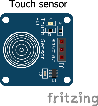
- Touch Sensor TTP223B
- Relay
- LED
- Arduino IDE (Integrated Development Environment)
- Embedded C/C++
- Fritzing
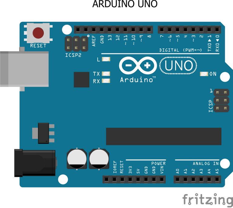
The Arduino Uno is a popular open-source microcontroller that uses the ATMEGA328P PIC (Programmable Integrated Circuit) chip developed by Arduino.cc. It has 14 digital I/O (Input / Output) pins and 6 analog I/O pins.
In this project, that is the stopwatch, the Arduino Uno microcontroller serves as the brain of the device, with which other components connected to it sends and receives instructions to and from respectively based on the code or instructions programmed to the microcontroller.
The voltage sensor is a sensor used in this tutorial is a DC voltage sensor, which makes the device to be able to sense and measure DC voltages. Voltage sensors are used widely in measuring and communicating electric voltage in components, equipment, devices, batteries or other sensors.
It has 3 pins which are:
- Vcc
- Gnd
- Signal
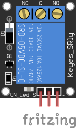
A typical relay has 5 terminals which consist of 2 coil terminals, the common terminal, the normally closed terminal, and the normally open terminal. But on the other hand, a relay module makes it easy to use the relay with microcontrollers like the Arduino Uno which has 6 terminals, which are the Vcc, GND, Source, NC (Normally Closed), NO (Normally Open), and the C (Common) terminals as shown in the image above. With the relay module, the source pin or terminal is been connected to any digital pin of the Arduino Uno microcontroller while the Vcc and GND goes straight to the Relays are majorly used as switches in lots of devices and equipment due to their ability to control larger appliances by applying a small voltage to their coil terminal.
By default the normally closed terminal and the common terminal of the relay module are connected together internally but when the relay is been energized the common switches from the normally closed to the normally open terminal thereby completing or connecting the broken connections together. Allowing the voltage coming from the power supply source to connect with the positive terminal of the appliance and thereby making it come on.
It also has 5 pins which are:
- Vcc
- Gnd
- Signal
- NO (Normally Open)
- NC (Normally Closed)
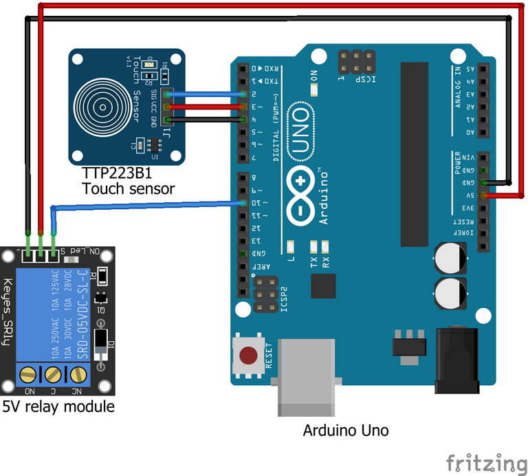
- Conneting the Voltage Sensor to the Arduino Uno
| Arduino Uno | Touch Sensor | |
|---|---|---|
| 1 | 5v | Vcc |
| 2 | Gnd | Gnd |
| 3 | D2 | Signal |
- Connecting the Relay Module to the Arduino Uno
| Arduino Uno | Relay Module | |
|---|---|---|
| 1 | 5v | Vcc |
| 2 | Gnd | Gnd |
| 3 | D10 | Signal |
//Touch Sensor Relay

 #define ctsPin 2

 int relayPin = 10;

void setup() {
  Serial.begin(9600);
  pinMode(touchPin, INPUT);
  pinMode(relayPin, OUTPUT);

}

void loop() {

  val = digitalRead(touchPin);

  if(val == HIGH && lightON == LOW){

    touched = 1-touched;
    delay(100);
  }

  lightON = val;

      if(touched == HIGH){
        Serial.println("Light ON");
        digitalWrite(relayPin, LOW);

      }else{
        Serial.println("Light OFF");
        digitalWrite(relayPin, HIGH);

      }

  delay(100);
}
Thanks for reading and visiting my blog 🤝. Kindly support this post by reblogging, upvoting, and commenting, it would be highly appreciated.
Images used in this post were all designed by me using frizting, a circuit design and simulation software, and canva.
Posted with STEMGeeks
Informative post.
Keep it up.
!1UP
You have received a 1UP from @thecuriousfool!
@oneup-curator, @stem-curator, @vyb-curator, @pob-curator, @neoxag-curator, @pal-curatorAnd they will bring !PIZZA 🍕
Learn more about our delegation service to earn daily rewards. Join the family on Discord.
PIZZA Holders sent $PIZZA tips in this post's comments:
@curation-cartel(17/20) tipped @techlhab (x1)
Join us in Discord!