Prototyping and Breadboarding your circuits
Good Morning! Most of my posts have covered the software side of my systems. I did go through wiring up the 12V LED light strips to the Pi with MOSFETS in Part III of the Raspberry Pi Home Automation series. I had also touched on my prototyping process in the same post.
- Plan, design, and build the circuit on a solderless breadboard
- Solder the circuit up using 'perf' board and deploy it for further testing
- Design the schematic using Fritzing or KiCad software and layout the gerber files for a PCB which you can then have built and sent to you.
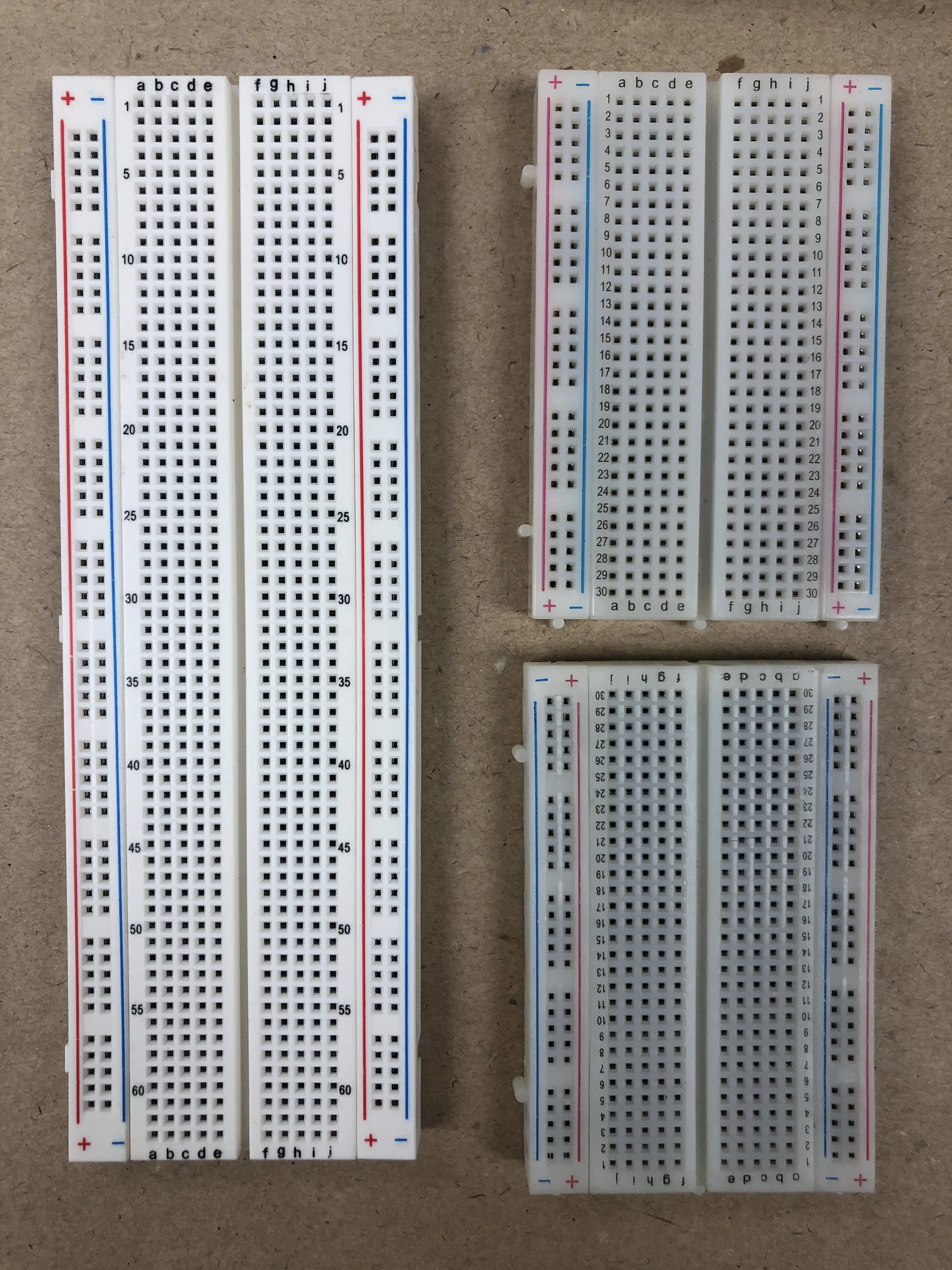
So lets start with part 1, building the circuit on a solderless breadboard. Hopefully you have a solderless breadboard available to you? The one on the left is a 830 point (or tie-point) and the 2 on the right are 400 point which specifies how many small holes are available to insert components or jumpers. Because they are solderless you can build and change your circuits very easily. There are some great videos and guides on how to use solderless breadboards. Briefly, all of the pins beside the red (+) line are connected together (There are 10 vertical groups of 5 in the 830 point and 5 groups of 5 in the 400 point boards) so you could use that as your connection points to the 3.3V for your Raspberry pi, or 5V for your Arduino. All of the vertical pins beside the blue (-) line are connected together as well so you could use that as the negative or ground connection point for your circuits.
 Every row of 5 horizontal holes are connected together which gives you 63 separate groups of 5 on either side of that center area. The center area is spaced so that you can plug in a DIP IC (Dual Inline Package, Integrated Circuit) and then access the pins on either side of it
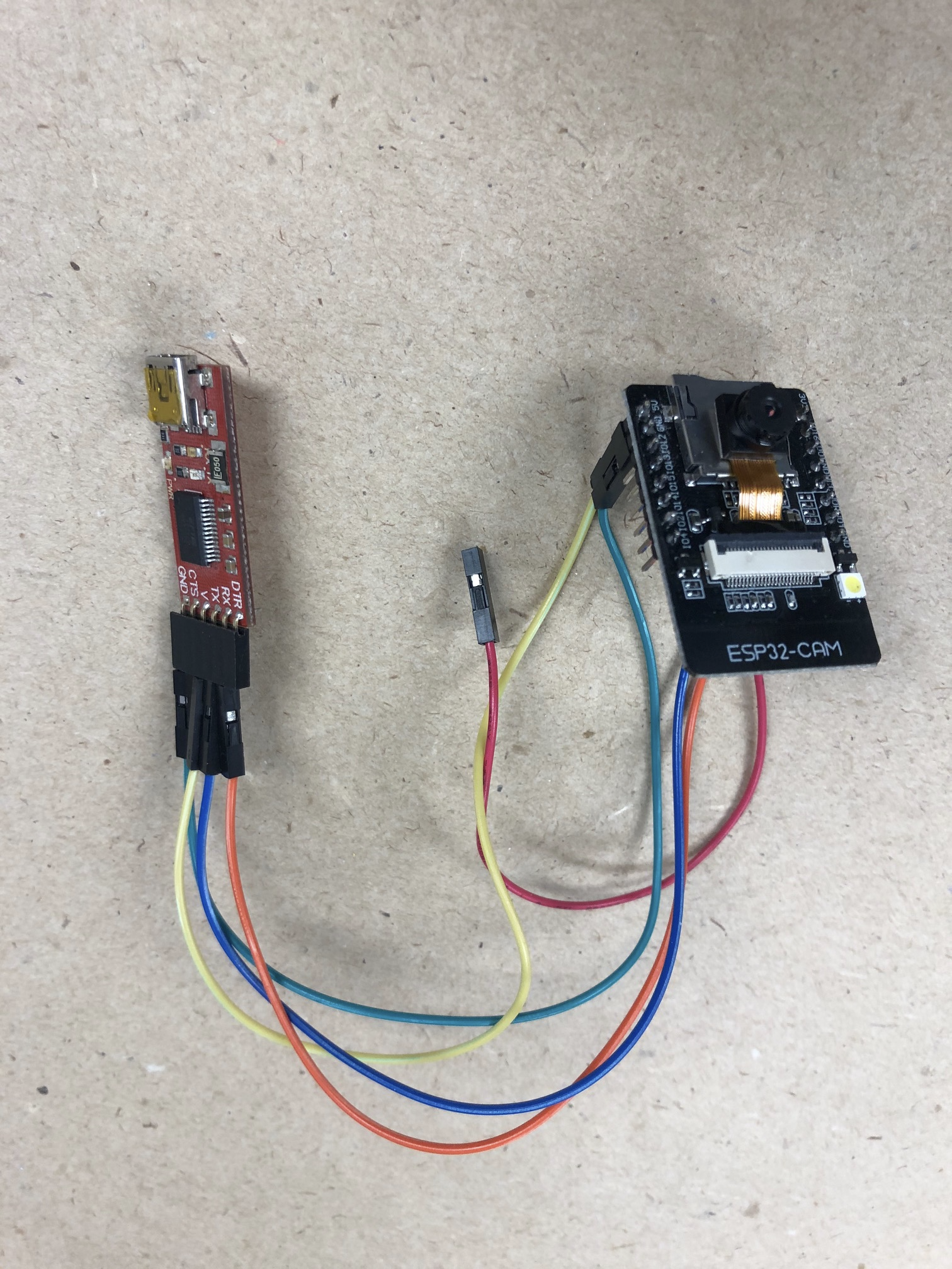
 And breadboards come in very small sizes and colours, here I'm using a couple of small breadboards to allow me to connect different circuits to an ESP-32
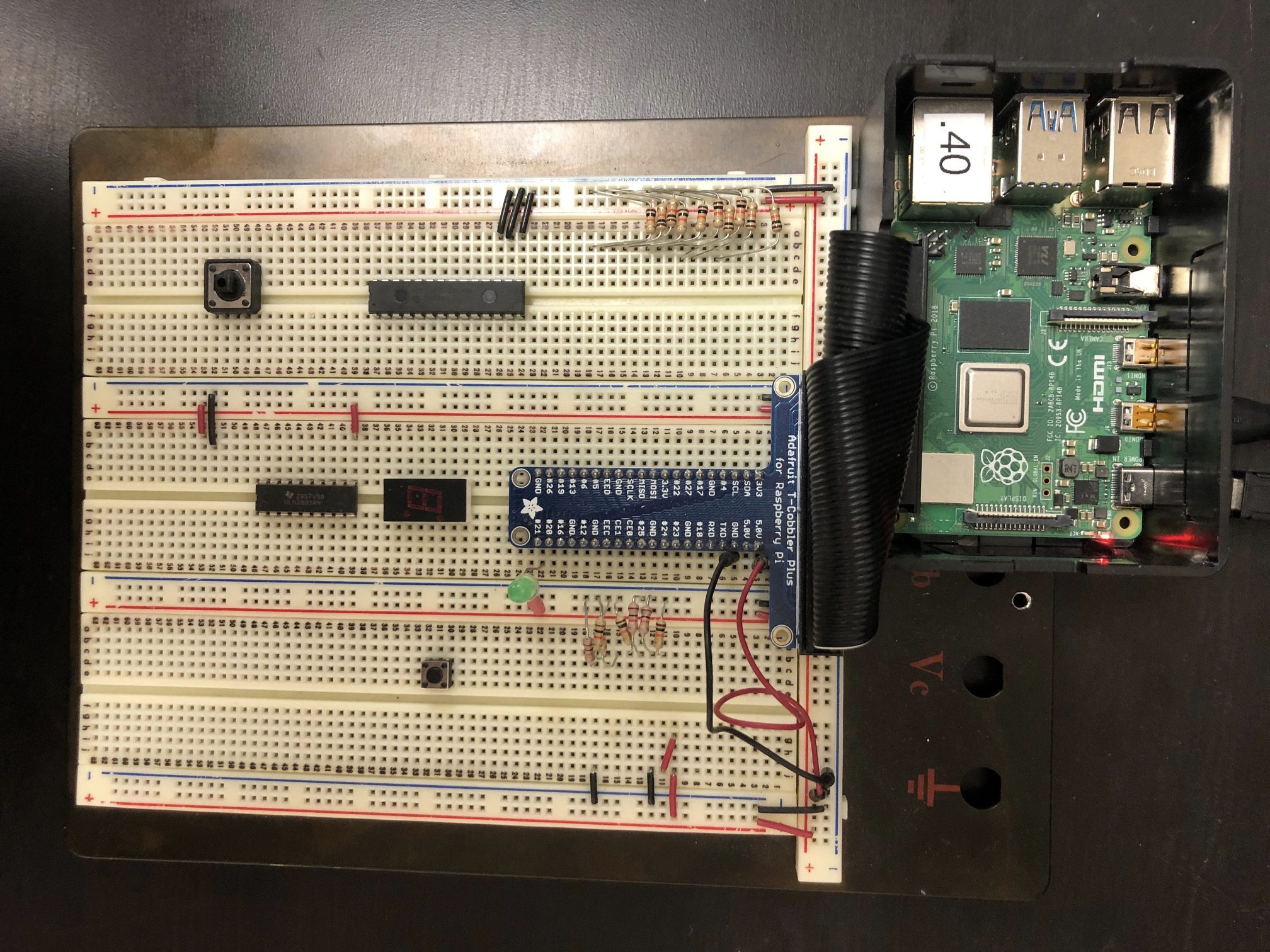 You can see on my breadboard how I've mounted the IC's in the centre of each breadboard strip, and you can see some of the small red & black jumper wires that are connecting various point to (+)3.3V or (-)ground. Doesn't this breadboard look very similar to @mytechtrail raspi08 breadboard. Notice how he has connected a Pi ZeroW to his breadboard and I'm using a Pi4. That goes to show the great flexibility of these devices.
 The rainbow coloured ribbon cable and the small red circuit board is known as a cobbler which is an easy way to connect to all 40 of the GPIO pins on the Pi and separate them out onto individual sockets on the breadboard.
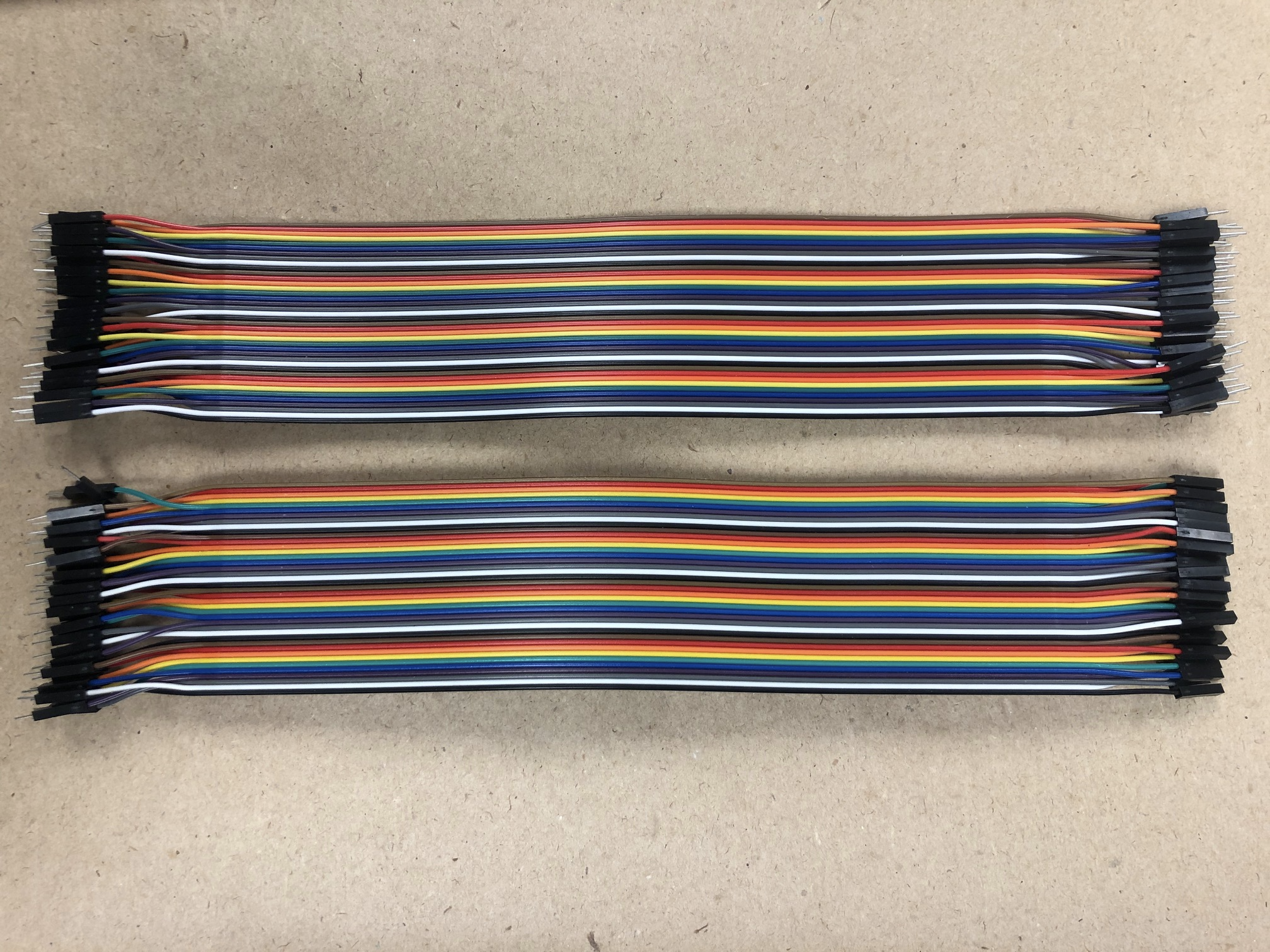 These sets of jumper wires often go by the name of Dupont Jumpers. They are used to connect the various different point on the breadboard by using the M>M (Male to Male) pins as show above. You can simply pull each one apart individually, you can see the gap in the insulation where the connectors are. I'll also simply use a piece of solid core 24ga CAT5 cable of which I always have random pieces laying around (grin) by stripping off the insulation from each end.
If I want to connect 2 devices that have the pins on them, I'll use the F>F (Female to Female) jumpers.
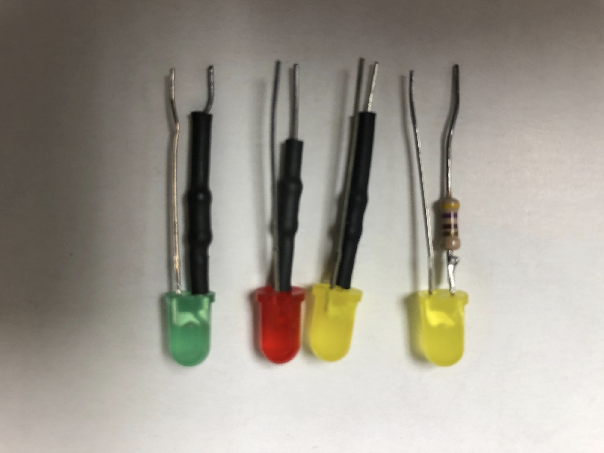
In my opinion, the most popular device to use with your breadboard is an LED (Light Emitting Diode) to test to see if the outputs are going high or low. When @mytechtrail was testing out his Node-Red install, you can see the LED that he has mounted on the small green breadboard to test the circuit, and his very largeLED's on his breadboard. You'll notice in most circuits you connect a current limiting resistor together with the LED to avoid damaging the LED (and potentially the device you have connected to it). You can see in my picture that I cut the Anode(+) lead of the LED short and solder the current limiting resistor onto it. Then I place some heat shrink tubing over that to prevent the 2 sides from touching each other (I had cut the heat shrink off the right LED to show the resistor soldered in place). This accomplishes several things:
- I always use a resistor with the LED, so this allows me to plug in 1 device rather than 2!
- I don't have to search for the darn resistors, which I tend to misplace (grin)
- I always solder the resistor on the Anode(+) side of the LED so I don't have to look for the small flat side of the LED (which is the Cathode(-)) to hook it up with the proper polarity.
- When I was teaching my basic soldering class, I would have the students make 3 or 4 of each colour, to learn how to solder and to make themselves a handy test device.
Some may be wondering what value of resistor to use (since you can't really tell from my pic, because it's out of focus). Remember Ohm's Law? E = IR, the voltage (E) across a device is equal to the current (I) through it multiplied by the resistance (R) of the device. I'm dealing with Pi's @ 3.3V and ESP-32's @ 5V so I use the larger voltage and goto the spec sheets of the LED to get maximum current that can flow through it. For my LED's that is 20mA, but I normally have several of these hooked up to a Pi and it's max output is ~51mA and ~16mA per pin from the element14 notes I've read. So what size to use?
- E=IR, so transpose R = E/I = 5V / 20mA = 250 ohms (minimum resistance)
- Because I want to limit the current to 10mA, R = 5V / 10mA = 500 ohms (maximum resistance)
- Somewhere between 250 - 500 ohms, and I'll normally use a 330 ohm resistor.
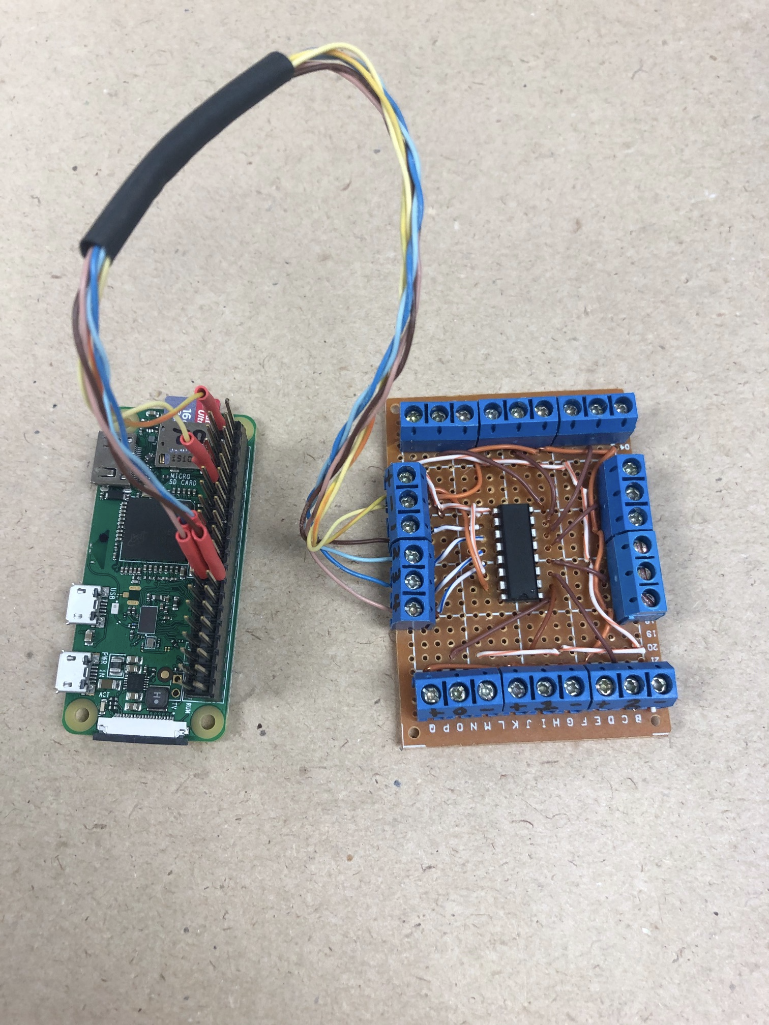
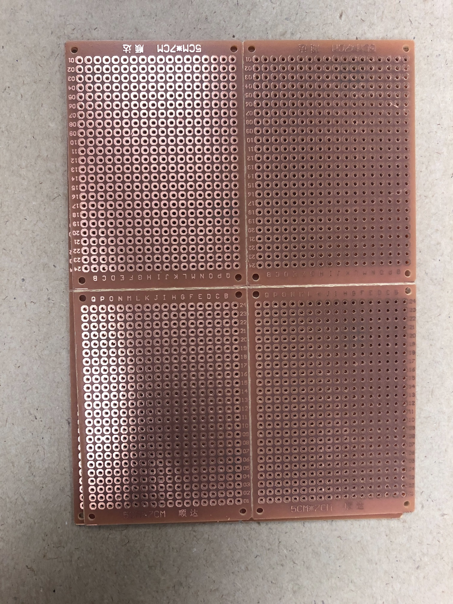
Once I've proven the circuit on the solderless breadboard, I'll move onto step 2, and solder up the circuit on perf board. The second pic shows the bottom of the perf board (this is a set of 4 boards and I break them apart when I use them) with each hole having it's own copper solder pad. On the upper pic, there is a 40 pin plug that is connected to the 40 pin GPIO strip on the Pi ZeroW so that I can disconnect it. Don't forget to use heat shrink tubing on any connections that have the potential to bend over and short out against each other.
 If you apply solder to 2 pins (sticking through the perf board) that are beside each other and add a little too much solder, it will jump across the 2 pads and 'bridge' them together. You have to be careful that you don't bridge connections that you want separate, if you look at L09 - L10 on my pic, you can see the scratch from my Xacto knife as I pulled it between the 2 sets of pads that appeared to be bridged. Best to check for short circuits, before you power it up....grin. I've got a box full of components that have been shorted out and I've "let out the magic smoke"(grin).
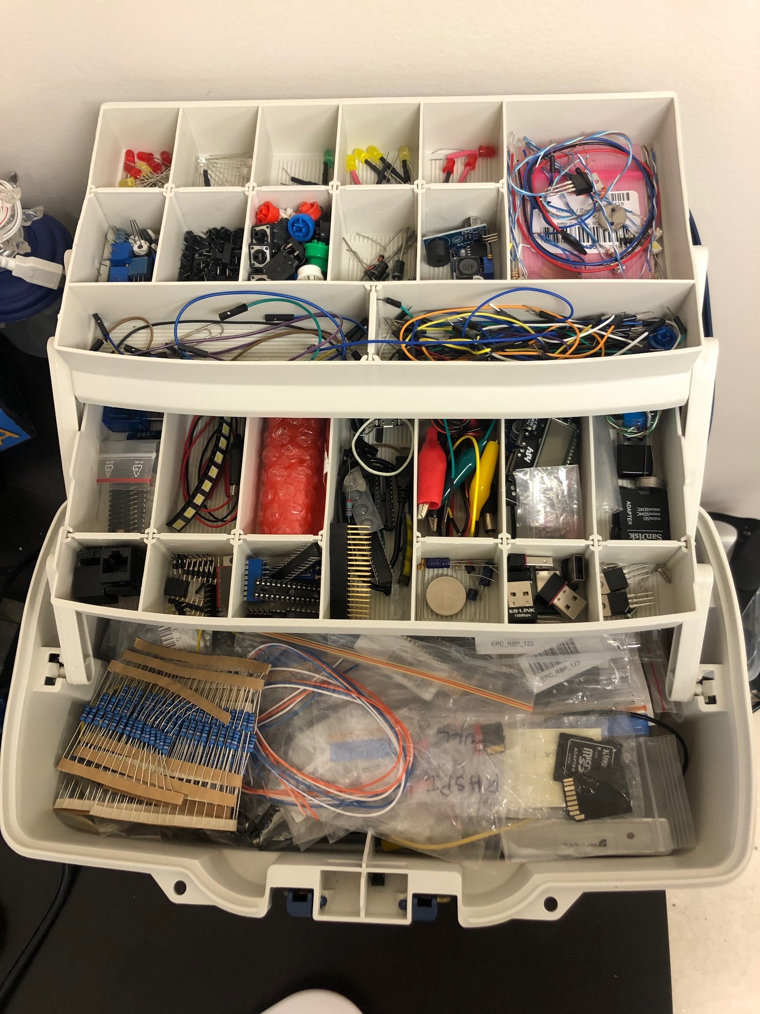
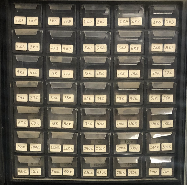
I find tackle boxes work great for storing and helping to organize all of the various components that you collect over time. For bigger batches of 'stuff' I also use the smaller rubbermaid sandwich size containers for storing common items together.
Thanks for viewing!
Robin
Posted with STEMGeeks
That's an awesome build. I need to get a post up showing a few things I've done, too; just plumb running out of time. What are you using the camera for?
Thanks, and yes please post the projects you've done! It would be great to see what others are making / building! The ESP32-CAM will be used for a motion sensing wildlife cam for my backyard. I live in a small town outside Calgary and don't have a fence across the back yard, so the deer (and wolves) cut through my yard on a regular basis. I see the tracks in the snow, but have never seen them and want to capture some pics. I hear your regarding lack of time, I've been fortunate to be able to post on a daily basis for the last few days, but I've got a 2nd Year Electrical Apprenticeship class starting tomorrow (Monday) morning and a Solar Power for Electricians course starting Tuesday evening, so the next few weeks will be spotty until things settle down!
Soldering the resistor to the LED is an interesting thing i never thought of.
Of course, i never misplace my 330 ohm resistors... because i have a BOX of them. :-p
Have you gotten into CNC cutting PCB boards?
Thanks for the reply @builderofcastles! We have a craft area downstairs where we both play and I've got limited space so I'll use the bins in my tackle box for the resistors (grin). If I'm in my Garage / ManCave I've got lots and lots of parts bins to keep everything sorted!
I'd love to have a small CNC router that I could use for PCB's but haven't invested in one yet. How about you?
Yes, but i never invested in the bits.