NodeMCU ESP8266 Microcontroller Review
Hello friends today we'll talk about NodeMCU ESP8266 Microcontroller.
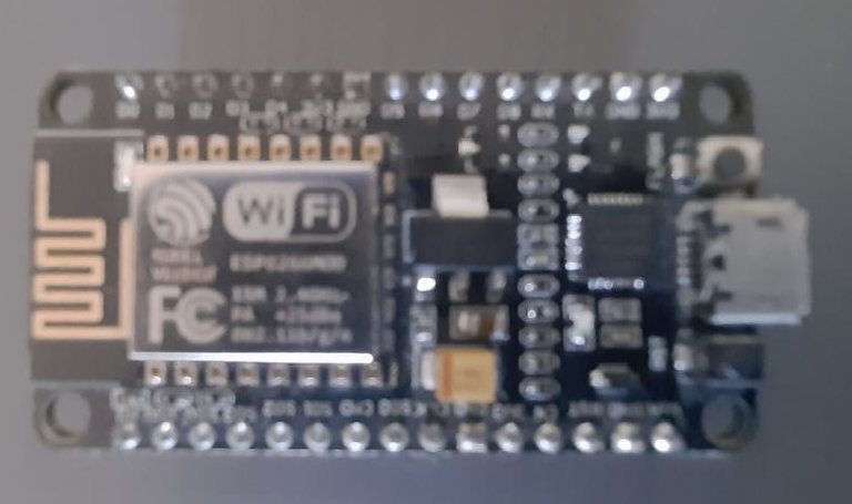
NodeMCU (Node Micro Controller Unit) is an open-source software and hardware development environment built around a low-cost system-on-chip (SoC) called the ESP8266. Designed and manufactured by Espressif Systems, the ESP8266 contains the key elements of a computer: CPU, RAM, network (WiFi), and even modern operating systems and SDKs. This makes it an excellent choice for various Internet of Things (IoT) projects.
For the simplest tasks, like turning it on or sending keystrokes to the on-chip "computer", you'll need to solder wires with the appropriate analog voltage to its pins. You also have to program it with low-level machine instructions that can be interpreted by the chip's hardware. This level of integration is not a problem when using the ESP8266 as an embedded controller chip in popular electronics products. This is a huge for hobbyists, hackers or students who want to experiment with it in their own IoT projects.
The Arduino project has created an open source hardware design and software SDK for its versatile IoT controllers. It also defines standard interfaces for interacting with sensors or other boards. But unlike NodeMCU, Arduino boards can have different types of CPU chips (usually ARM or Intel x86 chips), with memory chips and various programming environments. The flexibility of Arduino also means significant differences between different suppliers. For example, most Arduino boards don't have WiFi, and some even have serial data ports instead of USB ports.
NodeMCU Specifications
NodeMCU offers different variants. Common to all designs is the ESP8266 base core. Designs based on this architecture retain the standard 30-pin layout.
The most common variants of NodeMCU are Amica and LoLin, which has wider pin pitch and board size. The open source design of the base ESP8266 enables the market to continually design new variants of NodeMCU.
There are 4 power pins. The VIN pin and three 3.3V pins.
- VIN can be used to directly power the NodeMCU/ESP8266 and its peripherals. The power provided on VIN is regulated by the onboard regulator on the NodeMCU module - you can also provide 5V regulation to the VIN pin
- The 3.3V pin is the output of the onboard regulator and can be used to power external components.
- GND is the ground pin of NodeMCU/ESP8266
The I2C interface function can be implemented programmatically with a clock frequency of up to 100 kHz.
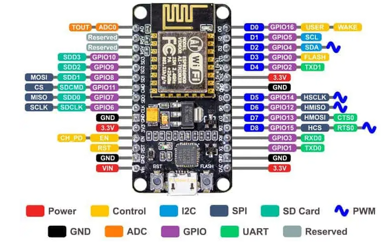
GPIO Pins
The NodeMCU/ESP8266 has 17 GPIO pins that can be programmatically assigned to functions such as I2C, I2S, UART, PWM, IR remote, LED lights, and buttons. Each digital enable GPIO can be configured as an internal pull-up or pull-down, or set to high impedance.
When configured as an input, it can also be set to be edge-triggered or level-triggered to generate CPU interrupts.
ADC channel
NodeMCU is embedded in a 10-bit precision SAR ADC. Both of these functions can be implemented by an ADC. Test the supply voltage of pin VDD3P3 and the input voltage of test pin TOUT. However, they cannot be implemented simultaneously.
UART pins
NodeMCU/ESP8266 has 2 UART interfaces (UART0 and UART1) that allow asynchronous communication (RS232 and RS485) with communication rates up to 4.5 Mbit/s. UART0 (TXD0, RXD0, RST0 and CTS0 pins) can be used for communication. But UART1 (TXD1 pin) has only one data transmission signal, so it is usually used to print logs.
SPI pins
NodeMCU/ESP8266 has two SPIs (SPI and HSPI) in slave and master mode. These SPIs also support the following general-purpose SPI functions:
- 4 SPI format transmission timing modes
- Shared clocks up to 80MHz and 80MHz
- FIFO up to 64 bytes
SDIO pin
The NodeMCU/ESP8266 has a Secure Digital Input/Output Interface (SDIO) for direct connection to SD cards. Supports 4-bit 25MHz SDIO v1.1 and 4-bit 50MHz SDIO v2.0.
PWM Pins
The board has 4 channels for Pulse Width Modulation (PWM). PWM outputs can be programmed and used to drive digital motors and LEDs. The PWM frequency range is adjustable from 100 Hz and 1 kHz.
Control pins included are:
- EN: When the EN pin is pulled high, the ESP8266 chip is activated. When pulled low, the chip runs at minimum power.
- RST: This pin is used to reset the ESP8266 chip.
- WAKE: The wake-up pin is used to wake the chip from deep sleep.
- Tiny Sine WaveControl pins are used to control NodeMCU/ESP8266.
USB to Serial Converter
Every NodeMCU has a built-in USB-to-serial converter. The board uses the CP2102 chipset, including the officially licensed Amica NodeMCU module. Another commonly used USB-to-serial converter is the CH340G, which is common on low-cost modules including LoLin units. Other designs may use drivers, including FTDI chipsets, but these are rare.
Depending on the operating system you are using with NodeMCU, the appropriate driver must be installed. In general, Windows 10 will recognize the CP2102 chipset right away, while the CH340G may need to be installed separately.
Drivers for the CP2102 can be downloaded from the Silicon Labs support site. Drivers are constantly evolving, ensuring the latest version has the fewest issues in your development environment.
It's always best to visit the original manufacturer to make sure you get the latest version of the driver.
CH340G Drivers ICWCH regularly maintains and updates drivers for CH340G. Versions of this driver are also available for Windows, Mac, Linux, and Android.
And that's all! I hope you like it and if you have any questions about this board please let me know in the comments.
Thank you for your time!
https://twitter.com/1492571933690499076/status/1580183925837922304
The rewards earned on this comment will go directly to the people( @ptmaker ) sharing the post on Twitter as long as they are registered with @poshtoken. Sign up at https://hiveposh.com.
Nice explanation about this microcontroller !

!1UP
Thank you :)
You have received a 1UP from @gwajnberg!
____
And they will bring !PIZZA 🍕.
Learn more about our delegation service to earn daily rewards. Join the Cartel on Discord.