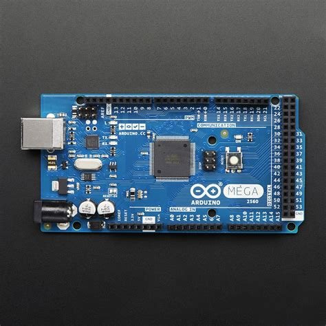
Arduino Mega 2560 Microcontroller
Hello friends, today we will talk about the Arduino Mega 2560 Microcontroller.
What is an Arduino Mega 2560?
Microcontroller boards like the "Arduino Mega" rely on the ATmega2560 microcontroller. It includes 54 digital input/output pins, of which 16 are analog inputs, 14 are used as PWM outputs, hardware serial port (UART) - 4, crystal oscillator - 16MHz, one ICSP header, one power supply jack, a USB connection, and the RST button.
This board basically contains everything needed to support a microcontroller. Therefore, the board can be powered by connecting it to a PC via a USB cable, battery, or AC-DC adapter.
By installing a backplane, the board can be protected from accidental discharges.
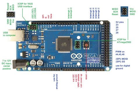
The SCL and SDA pins of the Mega 2560 R3 board are connected next to the AREF pin. Also, the two newest pins are located near the RST pin. One pin is IOREF, which allows the shield to set the voltage supplied by the Arduino board. The other pin is unassigned and will be reserved for future use. These boards can be used with any existing shield, but can accommodate the latest shields that use these extra pins.
Arduino Mega Specifications
- ATmega2560 is a microcontroller
- The microcontroller operates on 5 volts
- Recommended input voltage range is 7V to 12V
- Input voltage range is 6 volts to 20 volts
- There are 54 digital input/output pins, 15 of which provide PWM o/p.
- Analog input pins are 16
- 40mA DC current per input/output pin
- 50mA DC current for 3.3V pin
- Flash like 256 KB, 8 KB with the help of bootloader
- SRAM 8 KB
- Electrically Erasable Programmable Read-Only Memory (EEPROM) 4 KB in size
- Clock frequency (CLK) is 16 MHz
- The USB host chip used is MAX3421E
- Length 101.52 mm
- Width 53.3 mm
- The weight of this board is 36 grams
Arduino Mega Pin Configuration
Each pin on this board is assigned a specific function. All analog pins on this board can be used as digital I/O pins. The board offer flexible memory space and processing power, allowing work with different types of sensors without lag and are physically superior to other types of Arduino boards.
Pins 3.3V and 5V
These pins are used to provide a regulated O/P voltage of approximately 5V. This RPS (Regulated Power Supply) provides power to the microcontroller and other components used through the Arduino Mega Board. It can come from the board's Vin pin or a more stable voltage supply 5V otherwise the USB cable can provide different voltage regulation via the 3.3V0 pin. The maximum current consumption is 50mA.
Ground pin
The Arduino Mega Board includes 5 GND pins, one of which can be used when the project requires it.
Reset (RST) pin
The RST pin of this board can be used to rearrange the board. The board can be rearranged by setting this pin low.
VIN
The input voltage supplied to the board ranges from 7 volts to 20 volts. The voltage supplied by the power socket can be accessed through this pin. However, the output voltage to the board through this pin is automatically set to 5V.
Serial Communication
The board's serial pins TXD and RXD are used to transmit and receive serial data. Tx represents the transmission of information, while RX represents the received data. There are four combinations of serial pins on this board. For serial 0 it contains Tx(1) and Rx(0), for serial 1 it contains Tx(18) and Rx(19), for serial 2 it contains Tx(16) and Rx(17) , and finally for serial 3 it contains Tx(14) and Rx(15).
External Interrupt
External interrupts can be formed by using 6 pins, Interrupt 0(0), Interrupt 1(3), Interrupt 2(21), Interrupt 3(20), Interrupt 4(19), Interrupt 5(18). These pins generate interrupts in various ways by providing a LOW value, rising or falling edge, or by changing the value on the interrupt pin.
LED
This Arduino board contains an LED connected to pin-13, called digital pin 13. This LED can be driven according to the high and low value of the pin. This allows you to change your programming skills in real time.
AREF
The term AREF stands for Analog Reference Voltage, the reference voltage of the analog input
Analog pin
There are 16 analog pins on the board, labeled A0-A15. It is important to know that all analog pins on this board can be used like digital I/O pins. Each analog pin is accessible with 10-bit resolution and is capable of measuring voltages from GND to 5 volts.
I2C
I2C communication can be supported by two pins 20 and 21, where pin 20 represents the serial data line (SDA) for saving data, and pin 21 represents the serial clock line (SCL), which is mainly used in two Provides data synchronization device between pins
SPI communication
The term SPI is a serial peripheral interface used to transfer data between a controller and other components. The four pins MISO (50), MOSI (51), SCK (52) and SS (53) are used for SPI communication.
Length and Width
The dimensions of the Arduino Mega 2560 board mainly include length and width, such as 101.6 mm or 4 inches x 53.34 mm or 2.1 inches. It is relatively superior to other types of boards on the market. However, the power jack and USB port are slightly larger than specified.
Shield Compatibility
The Arduino Mega works with most protection devices used in other Arduino boards. Before you plan to use a protector, make sure that the protector's operating voltage is well suited to the voltage of the circuit board. Most protectors operate at 3.3V, otherwise 5V. However, high operating voltage protection devices can damage the circuit board.
Also, the shield's header should vibrate with the Arduino board's header pins. To do this, all you need to do is connect the shield to the Arduino board and put it into operation.
Programming
The Arduino Mega 2560 can be programmed using the IDE (Arduino Software) and supports the C programming language. This is the code sketch in software that is burned in software and then pushed to the Arduino board using a USB cable.
The Arduino Mega board includes a bootloader that eliminates the need to use an external burner to burn program code into the Arduino board. Here, the bootloader can communicate via the STK500 protocol.
When we compile and burn the Arduino program, we can unplug the USB cable to disconnect the power to the Arduino board. Whenever you plan to use the Arduino board for your project, power can be supplied either from the power jack on the board or from the Vin pin.
Multitasking
Another feature is multitasking, whenever the Arduino Mega Board comes in handy. But the Arduino IDE software does not support multitasking, but you can use other operating systems, namely RTX and FreeRTOS, to write C programs. This can be used flexibly in your personal custom builders with the help of ISP connectors.
And that's all! I hope you like it and if you have any question about this microcontroller, please let me know in the comments.
Thank you for your time!
https://twitter.com/1492571933690499076/status/1587799769849729026
The rewards earned on this comment will go directly to the people( @ptmaker ) sharing the post on Twitter as long as they are registered with @poshtoken. Sign up at https://hiveposh.com.
This is another interesting microcontroller

!1UP
Yes it is! And powerful
You have received a 1UP from @gwajnberg!
@stem-curator
And they will bring !PIZZA 🍕.
Learn more about our delegation service to earn daily rewards. Join the Cartel on Discord.
Thats something that i would like to learn... I have a raspberry pi zero to play with but this one is very interesting. How much it costs?
It costs around $10 on aliexpress if you dont care to wait 3 months to get it. But it worth the price!