MY TODAY ASSIGNMENT
Hi friends, today I will be telling you guys base on my today assignment. The assignment is to build a astable Multivibrators circuit so when I got home. I decided to go market to buy the components which are the following.
9v battery.
battery clips
2: 2.2k resistor.
2: 56k resistor.
2: 4.7uf capacitor.
2: LED.
2: BC 108 transistor.
1: Vero board.
lets take the functions of the following one after the other.
This is the point when the current is been generated. it's a DC (direct current)
it limit the flow of current. The resistor don't have polarity ( i.e it doesn't have negative and positive line)
The capacitor store current. it has polarity the longer lag of a capacitor is the positive side and the shorter lag is always the negative side of any Capacitor
it indicates lights whether the circuit is functioning or not working and it has polarity the longer lag of any LED is the positive side and the shorter lag is the negative side of any LED.
It is a 3-terminal electronics device made up of semi conductor .it transfer current across resistor in a circuit. it has polarity and it is called Emitter, base and collector. Emitter is middle lag of a transistor base is first lag of a transistor and collector is the last lag of a transistor.
This is the battery clips that has terminals of clipping to enable current flow through the circuit.
it's a solderable board that is use for practicals
let's see the circuit diagram
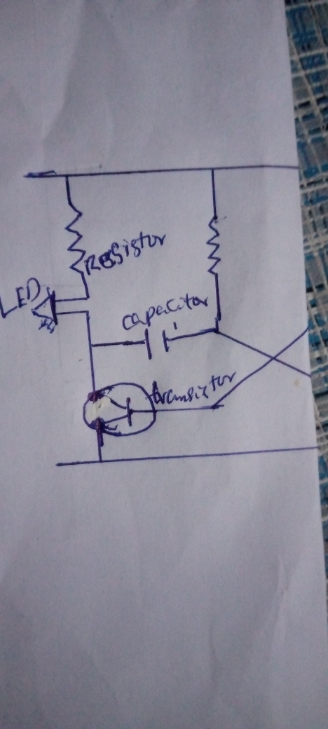
First part of the circuit diagram
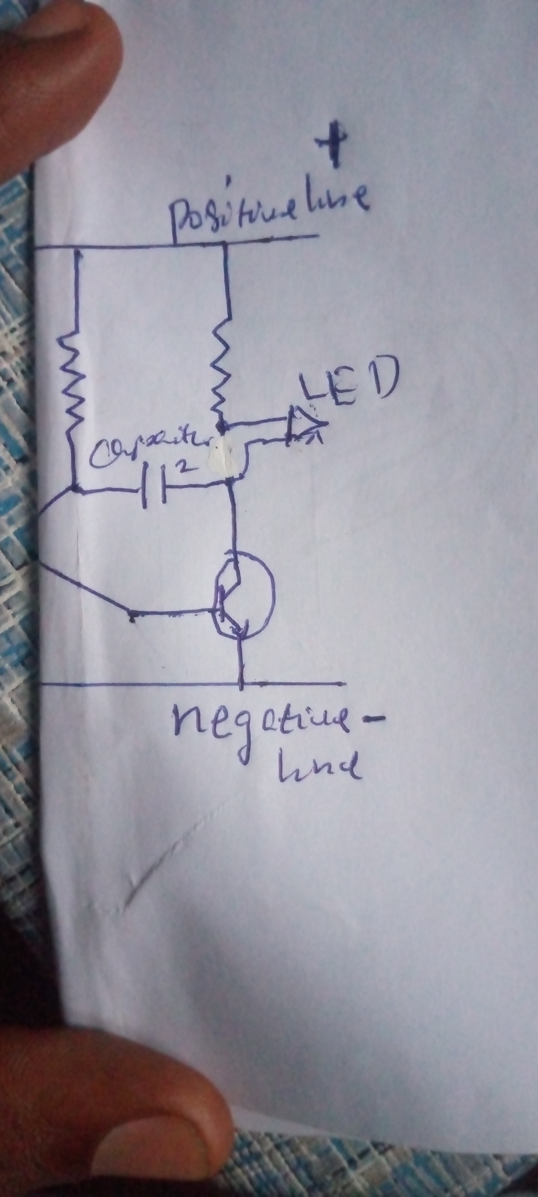
Second part of the circuit diagram
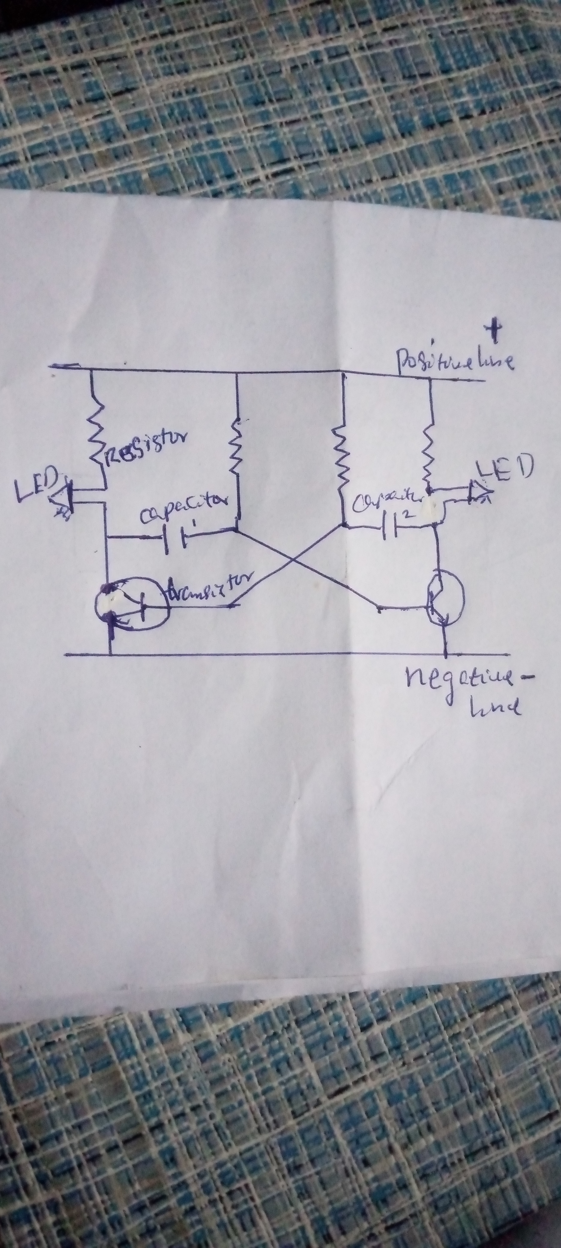
The full circuit diagram
In the circuit diagram, The resistors are Connected in parallel and they're all connected in positive line. In the half circuit diagram the first resistor is connected to the positive of the LED and the negative legs of the LED is connected to positive of the capacitor and goes straight to one leg of the transistor and the second lag of the transistor is connected to the negative line.
similarly
The second resistor is connected to the negative of the capacitor and and goes straight to the one leg of the second transistor(which is connected in the middle lag of the transistor) in the 2nd half diagram of the circuit.
In the other half part circuit diagram the first resistor is connected to the positive of the LED and the negative legs of the LED is connected to positive of the capacitor and goes straight to one leg of the transistor and the second lag of the transistor is connected to the negative line
similarly
The second resistor is connected to the negative of the capacitor and and goes straight to the one leg of the first transistor(which is connected in the middle lag of the transistor) in the 1st half part diagram of the circuit.
if you follow the procedure well you can see that everything is been connected on the full circuit diagram.
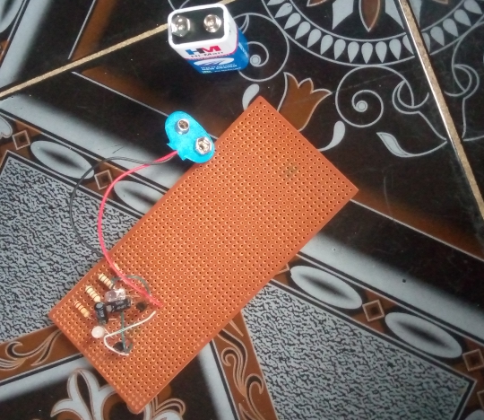
I have done these circuit, it's functioning very well and I would like my Hive friends to try these at your own convenient time.
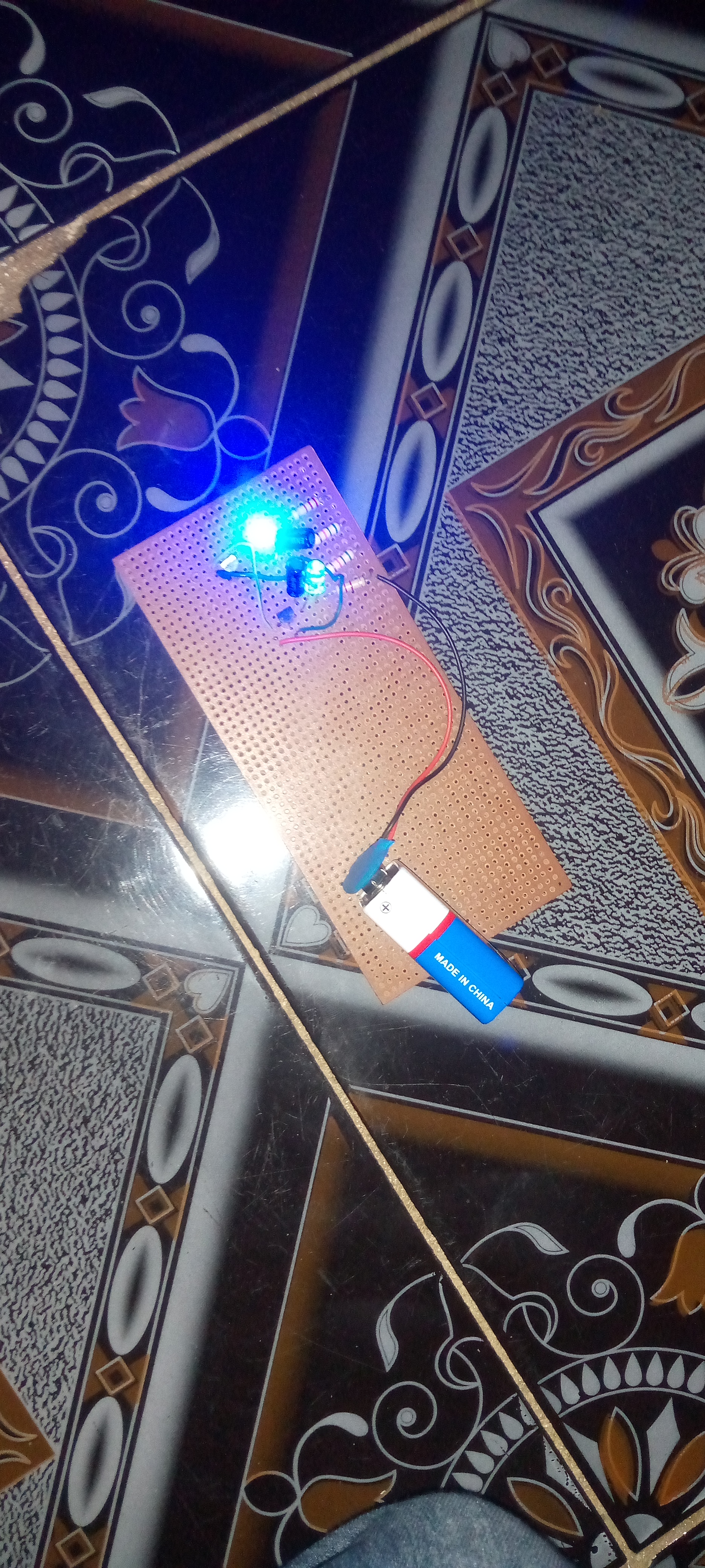
Result : The result is that the two LED will be blinking light.
Thank you all 💛