Electro-Hydraulics Basics: Automating using Logic Controller
In the previous blog, we create a circuit that enables us to use a logic controller to control the motion of a double-acting cylinder. In this blog, we elevate the discussion and create a simple circuit that automates a double-acting cylinder using a logic controller. The process to be simulated is describe as
A container of washers is to be dipped in and out of the cleaning bath. The start button initiate the washing. The dipping on the cleaning bath is continuous until stop button is pressed. Once stop button is pressed, the container returns to initial position.
The process involves continuous repetition of extending and retracting of double-acting cylinder. The logic controller receives the signal from the sensors to be able to achieve the process. In the next section, we create and discussed the circuit in details.
2. Circuit and Simulation
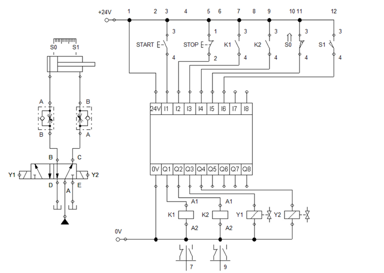
Figure 1: Electro-Hydraulic Circuit with Logic Controller
Similar to the previous blog, we used a double solenoid 5/2 way directional control valve as the control element for the double-acting cylinder while a pair of one-way flow control is given to control the speed. For the controller, we set a pair of push button, relay contact and sensor as the input while a pair of relay coil and solenoid at the output.
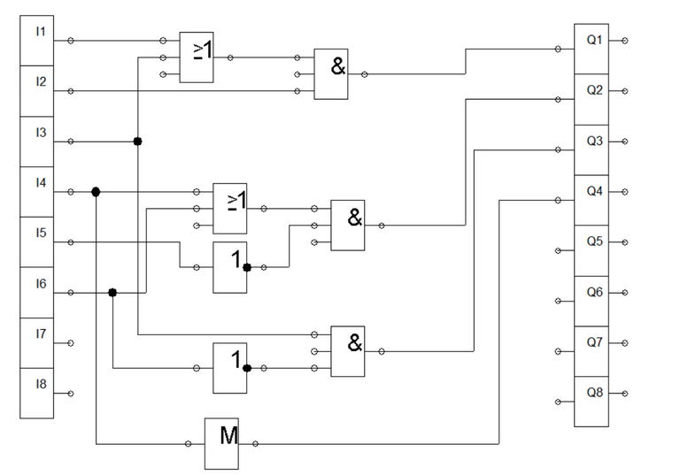
Figure 2: Logic Control Circuit
To activate the relay K1, we set start button and contact K1 as the input to an OR gate and the output is connected to an AND gate with the start button. Relay K1 sustains activation while start button activate the relay. The stop button is placed to stop the automation. In Figure 3, we can see the activation requirement for relay K1. When relay K1 is activated, solenoid Y1 is also activated. Solenoid Y1 is actuated by a combination of an AND and a NOT gate. The input to the and gate is the signal from contact K1 and the inverted signal from sensor S1.
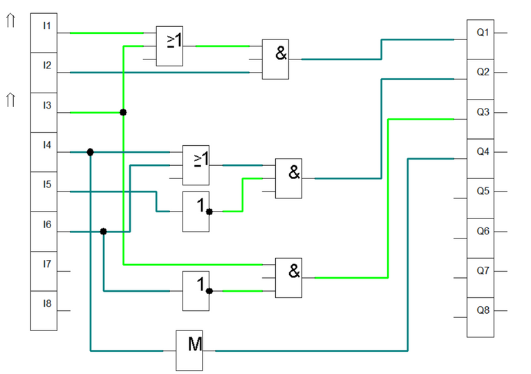 Figure 3: K1 and Y1 is activated.
For relay K2, we set sensor S1 and relay K2 as the input to an OR gate and the output is feed to an AND gate together with the inverted value of sensor S0. When K2 is activated, solenoid Y2 is activated at the same time hence it is driven by relay contact K2. Solenoid Y2 retracts the cylinder to initial position. The inverted signal coming from the sensor enable us to automate the process. The activation of relay K2 is shown in Figure 4 while the simulation is in Figure 5.
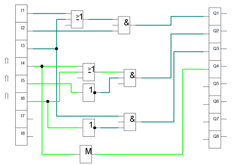
Figure 4: K2 and Y2 is activated.
Figure 5: Simulation
3. Conclusion
In this blog, we create a electro-hydraulic circuit that uses logic controller to automate a process We used a combination of logic gates to encode the required condition. Also, we used an inverted signal to cut off the activation of the relay every time the sensor detects a new position of the cylinder. The important points to remember in automating a process with logic controller is to know when to add the inverted signal (coming from NOT gate) to stop or start the relays.
4. References
[1] Hydraulic Basic Level. online access
[2] Hydraulic Advance Level. online access
[3] Electro-Hydraulic Basic Level. online access
[4] Electro-Hydraulic Advance Level. online access
(Note: All images and diagram in the text are drawn by the author (@juecoree) except those with separate citation.)
If your are interested in pneumatic and hydraulic series, you can read:
Pneumatic and Electro-pneumatic
1. Pneumatic Basics: Direct Control
2. Pneumatic Basics: Indirect Control
3. Pneumatic Basics: AND and OR Logic
4. Pneumatic Basics: Memory Circuit and Speed Control
5. Pneumatic Basics: Dependent control
6. Pneumatic Basics: Multiple Actuators
7. Electro-pneumatic Basic: AND and OR Logic
8. Electro-pneumatic Basics: Interlocking, Latching and XOR logic
9. Electro-pneumatic Basics: Distribution of Workpiece
10. Electro-pneumatic Basic: Ejecting a workpiece
11. Electro-pneumatic Basics: Basic Automation
12. Electro-pneumatic Basics: Automation with Counter
12. Electro-pneumatic Basics: Automating with Timer
13. Electro-pneumatic Basics: Cementing Press (Time Dependent Control)
14. Electro-pneumatic Basics: Embossing Device
15. Electro-pneumatic Basics: Bending Device
16. Electro-pneumatic Basics: Introduction to Logic Module
17. Electro-pneumatic Basics: Automating with Logic Controller
18. Electro-pneumatic Basics: Logic Controller for Multiple Actuators
19.Electro-pneumatic Basics: Time-dependent control with Logic Controller.
Hydraulics and Electro-Hydraulic
20. Hydraulic Basics: Direct Control
21. Hydraulic Basics: Indirect Control
22. Hydraulic Basics: Dual Pressure Value and the AND Logic
23. Hydraulic Basics: Shuttle Valve and the OR Logic
24. Hydraulic Basics: Sequencing Multiple Cylinders (Actuators)
25. Hydraulic Basics: Automating Multiple Cylinders (Actuators)
26. Electro-Hydraulic Basics: Direct and Indirect Control (Part 1 of 2)
27. Electro-Hydraulic Basics: Direct and Indirect Control (Part 2 of 2)
28. Electro-Hydraulic Basics: Two ways in Implementing AND logic
29. Electro-Hydraulic Basics: Two ways in Implementing OR logic
30. Electro-Hydraulic Basics: Circuit with ON and OFF-delay Timer
31. Electro-Hydraulic Basics: Automating Processes (1 of 3)
32. Electro-Hydraulic Basics: Automating Processes using Timer (2 of 3)
33. Electro-Hydraulic Basics: Automating Processes with Counter (3 of 3)
34. Electro-Hydraulic Basics: Controlling Multiple Cylinder
35. Electro-Hydraulic Basics: Automating Multiple Cylinder
36. Electro-Hydraulic Basics: Controlling Cylinder using the Logic Module
Posted with STEMGeeks