Electro-Hydraulic Basics: Controlling Multiple Cylinder
In this blog, we create and discussed a circuit that allow us to manipulate or control multiple cylinder. Also, we emphasize on how to sequence the motion of each cylinder according to the process description. The problem is describe as
Boxes are moved from a vertical stack into a conveyor. Cylinder A pushed the boxes from the stack and Cylinder B transfers the box to the conveyor. Cylinder B retracts at after the box is push into the conveyor while cylinder A retracts after cylinder B returns to initial state. The process is activated by pressing a button. To confirm the cylinder position at any given time, a pair of limit switch is placed in each cylinder.
We define the sequence of actions done by the cylinder. The sequence of motion are A+, B+, B-, and A-. This serves as our guide in configuring the electrical controller for our circuit. By the way, the minus sign indicates the cylinder is retracted while plus sign is for extended cylinder. In the next section, we show the circuit and discussed in details.
2. Circuit and Simulation
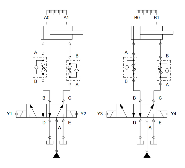
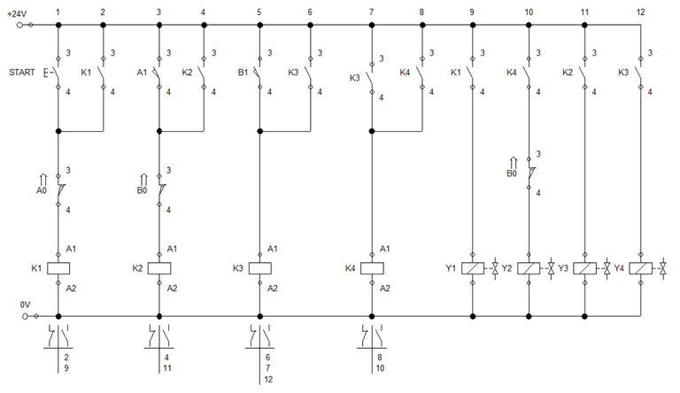
Figure 1: Electro-Hydraulic
Both cylinder in our circuit is driven by a 5/2 way directional control valve. The cylinder's motion is detected by a pair of sensor. Each cylinder have one sensor each for retracted and extended position. To limit the speed of motion, each cylinder has a pair of one-way flow control that is set to 50%. The one-way flow control enables us to clearly see the transition between each position during simulation.
For the electrical control, we used four set of relay and solenoid to achieve the described process. For the A+ , we set the start button in parallel with contact K1. Then, it is connected in series to sensor A0 and the relay. Solenoid Y1 is connected to contact K1. When the push button is pressed, the electricity activate relay K1. Latching contact K1 sustains activations as all relay K1 in the circuit switched to close position. Solenoid Y1 is activated simultaneously with relay K1. The solenoid actuated 5/2 way DCV opens port B to extend the cylinder. Once successfully extended, K1 sustains activation until retracted back to initial state.
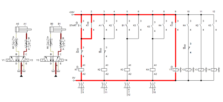
Figure 2: Start button is pressed.
To extend cylinder B and fulfill B+, we connect sensor A1 in parallel to latching contact K2. It is combined in series with sensor B0 and relay K2. When cylinder A reach full extended length, A1 closes and enables electricity to activate relay K2. It result to the activation of solenoid Y3 as K2 contact closes. The cylinder B extends as port B of the 5/2 way DCV at cylinder B opens up and fluid pressure actuates the cylinder. When the cylinder reaches full extended length, sensor B1 is activated.
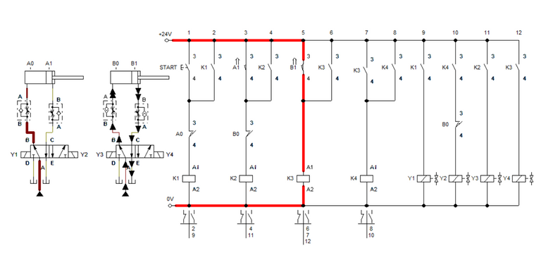
Figure 3: Cylinder B is fully extended.
Hence cylinder B is fully extended, sensor B1, which is parallel to latching K3, activates the series relay coil K3. Activating relay K3 switched the position of all latching contacts K3. Solenoid Y4 is activated when K3 contact switched to closed position and electricity passes through it. Solenoid Y4 is responsible for retracting cylinder B. Once it reached the full retracted position, sensor B0 is reactivated and enables latched contacts to activate K4.
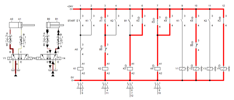
Figure 4: Cylinder B returns to retracted position.
Solenoid Y2 is activated when K3 closes and allows electricity to flow through it. It enables port C at cylinder A to open and retract cylinder A. Hence K1 is still engaged, we set sensor A1 to cut it when the cylinder returns to retracted position. The simulation is shown in Figure 5.
3. Conclusion
In this blog, we discussed on how we correctly assigned the sensors of multiple actuators in electro-hydraulic circuit. we used an strategically placed sensors and relay to achieved the A+, B+, B-, and A- sequence. In the circuit, we used switches but in a practical setting, there are variety of sensors that can be used. Fully understanding the sequence of motion or the process itself aids in correctly assigning the sensors across the circuit.
4. References
[1] Hydraulic Basic Level. online access
[2] Hydraulic Advance Level. online access
[3] Electro-Hydraulic Basic Level. online access
[4] Electro-Hydraulic Advance Level. online access
(Note: All images and diagram in the text are drawn by the author (@juecoree) except those with separate citation.)
If your are interested in pneumatic and hydraulic series, you can read:
Pneumatic and Electro-pneumatic
1. Pneumatic Basics: Direct Control
2. Pneumatic Basics: Indirect Control
3. Pneumatic Basics: AND and OR Logic
4. Pneumatic Basics: Memory Circuit and Speed Control
5. Pneumatic Basics: Dependent control
6. Pneumatic Basics: Multiple Actuators
7. Electro-pneumatic Basic: AND and OR Logic
8. Electro-pneumatic Basics: Interlocking, Latching and XOR logic
9. Electro-pneumatic Basics: Distribution of Workpiece
10. Electro-pneumatic Basic: Ejecting a workpiece
11. Electro-pneumatic Basics: Basic Automation
12. Electro-pneumatic Basics: Automation with Counter
12. Electro-pneumatic Basics: Automating with Timer
13. Electro-pneumatic Basics: Cementing Press (Time Dependent Control)
14. Electro-pneumatic Basics: Embossing Device
15. Electro-pneumatic Basics: Bending Device
16. Electro-pneumatic Basics: Introduction to Logic Module
17. Electro-pneumatic Basics: Automating with Logic Controller
18. Electro-pneumatic Basics: Logic Controller for Multiple Actuators
19.Electro-pneumatic Basics: Time-dependent control with Logic Controller.
Hydraulics and Electro-Hydraulic
20. Hydraulic Basics: Direct Control
21. Hydraulic Basics: Indirect Control
22. Hydraulic Basics: Dual Pressure Value and the AND Logic
23. Hydraulic Basics: Shuttle Valve and the OR Logic
24. Hydraulic Basics: Sequencing Multiple Cylinders (Actuators)
25. Hydraulic Basics: Automating Multiple Cylinders (Actuators)
26. Electro-Hydraulic Basics: Direct and Indirect Control (Part 1 of 2)
27. Electro-Hydraulic Basics: Direct and Indirect Control (Part 2 of 2)
28. Electro-Hydraulic Basics: Two ways in Implementing AND logic
29. Electro-Hydraulic Basics: Two ways in Implementing OR logic
30. Electro-Hydraulic Basics: Circuit with ON and OFF-delay Timer
31. Electro-Hydraulic Basics: Automating Processes (1 of 3)
32. Electro-Hydraulic Basics: Automating Processes using Timer (2 of 3)
33. Electro-Hydraulic Basics: Automating Processes with Counter (3 of 3)
Posted with STEMGeeks
Congratulations @juecoree! You have completed the following achievement on the Hive blockchain and have been rewarded with new badge(s) :
You can view your badges on your board and compare yourself to others in the Ranking
If you no longer want to receive notifications, reply to this comment with the word
STOPCheck out the last post from @hivebuzz: