Reparación de una fuente de poder ATX (Parte 1) | Repairing of an ATX Power Supply (Part I)

Hola #GEMS! ¡Bienvenidos a mi post! // Welcome to my post #HIVE!
Hola #GEMS! ¡Bienvenidos a mi post! // Welcome to my post #HIVE!
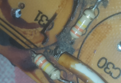
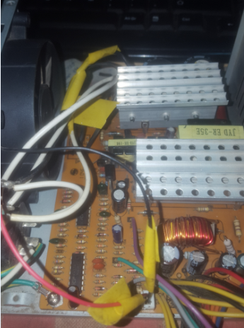
Today I bring you one of my repairs, but unfinished for lack of spare parts. I make a short summary. A friend of mine comes to my workshop with her dead computer, making the preliminary diagnoses, detecting the main fault was in the power supply, so I decided to download it from the equipment and check it. When disassembling it, and making the corresponding revisions, detect the following faults that appear in the following photo:
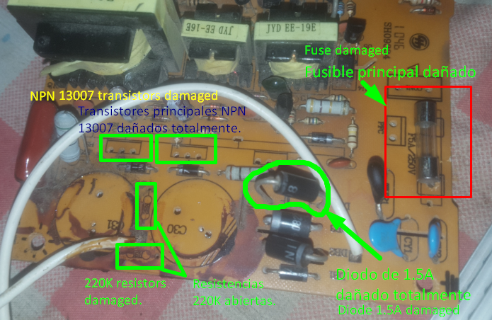
As you can see in the image above, there are too many damaged components. I couldn't determine what could have caused the fault, but the damage started with the transistors, and then in its path it damaged everything that was associated with them (The resistors, the diode and of course, the fuse to protect itself from not damaging more components) .
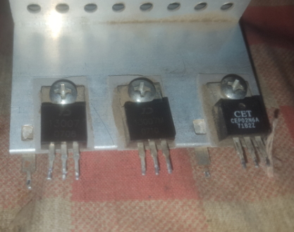
Estos son los transistores. Actúan como interruptores de potencia. Cuando se dañan, todos sus terminales se cruzan y causan corto-circuito.
These are the transistors. They act as power switches. When they are damaged, all their terminals cross and cause a short circuit.
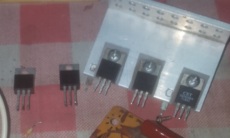
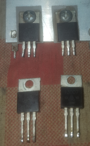
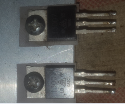
Del lado izquierdo tenemos los dos transitores (usados, reciclaje..) para reemplazar los dañados, del lado derecho. El último que se ve de lado derecho es un transistor MOFSET, no se preocupen, está bueno.
On the left side we have the two transients (used, recycling ...) to replace the damaged ones, on the right side. The last one seen on the right hand side is a MOFSET transistor, don't worry, it's good.
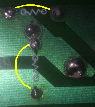
Sometimes we won't be able to get the 220K resistors, so I had to improvise with 2 330K. According to my teacher, to function, to leave them, if not, to remove them.
También colocamos los 2 Capacitores de la entrada AC.
We also put the 2 Capacitors of the AC input.
Ahora procedemos a reemplazar los transistores.
Now we proceed to replace the transistors.
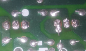
Listo, colocados en su lugar.
Done, put in place.
Ahora intentamos encajar los transistores.
Now we try to fit the transistors.
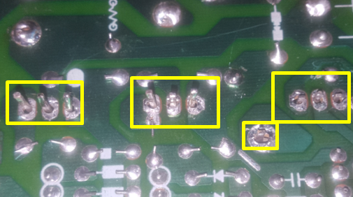
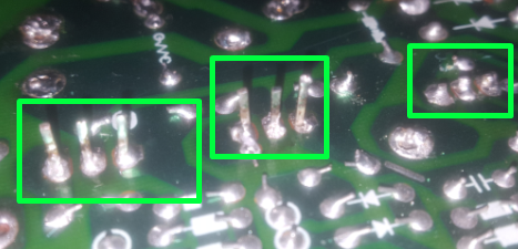
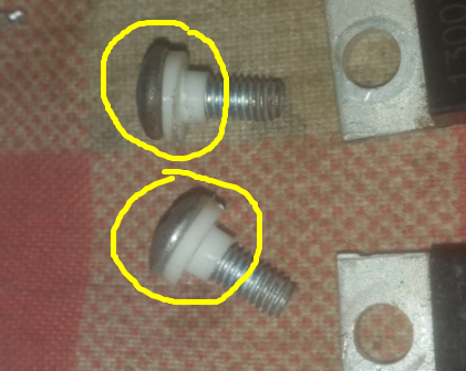
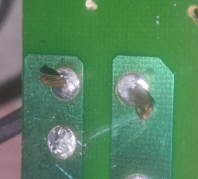
With the 3 correct welds, we now proceed to the next step. First and foremost we have to remove those excess terminals, since they can touch the metal of the chassis and there we would have a bigger problem.
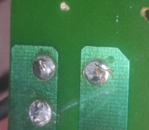
Así más o menos deben de quedar. Deben estar siempre a ese tipo de detalles para evitar futuros problemas al momento de armar y tengas que volver a hacer todo.
So more or less should be. They should always be at that kind of detail to avoid future problems when assembling and you have to do everything again.
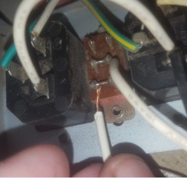
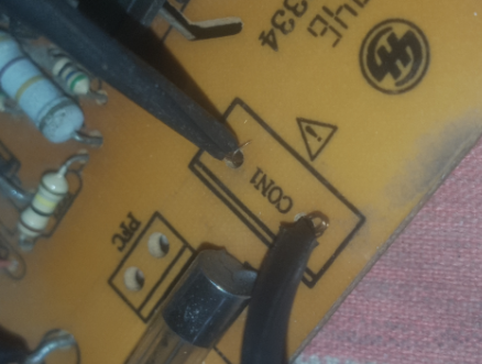
Este cable tuve que despegarlo al momento de desarmar la fuente ya que no me dejaba hacer nada con la placa, el cable era muy corto. Así que procedí a resoldarlo nuevamente.
This cable had to be detached at the time of disassembling the source since it did not allow me to do anything with the plate, the cable was very short. So I proceeded to resolve it again.
Con la soldadura lista, procedemos ahora con el siguiente paso.
With the weld ready, we now proceed to the next step.
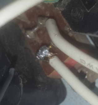
Estos cables también tuve que despegarlos, así que procedí a resoldarlos. Muchas veces nos tocará hacer esto ya que el espacio es muy limitado y necesitamos trabajar lo más cómodo posible.
I also had to detach these cables, so I proceeded to resolve them. Many times we will have to do this since space is very limited and we need to work as comfortable as possible.
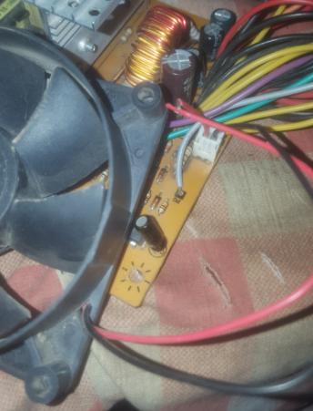
We place the fan cooler in its connector to proceed with the assembly. Now after this we proceed with each measurement of each connector.
Medición del conector PWR_ON, el cual consiste en enviar una señal de 5V aproximados para que, al ser puenteado con GND, encienda la fuente de alimentación.
Measurement of the PWR_ON connector, which consists of sending an approximate 5V signal so that, when bridged with GND, it turns on the power supply.
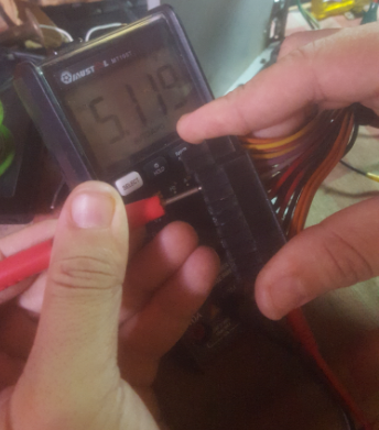
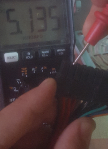
Conector de STAND_BY, medición correcta. El valor de referencia siempre va a ser 5V en ambos conectores.
STAND_BY connector, correct measurement. The reference value will always be 5V on both connectors.
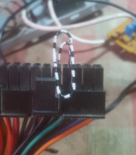
Procedemos a puentear el cable verde y el cable negro para encender la fuente de poder y proceder con la medición de los voltajes restantes (+12V, +5V, +3.3V y -12V).
We proceed to bridge the green wire and the black wire to turn on the power source and proceed with the measurement of the remaining voltages (+12V, +5V, +3.3V and -12V).
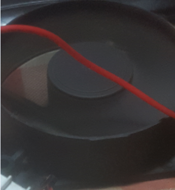
Al puentear ya tenemos el primer indicio de que vamos por buen camino. El fancooler arrancó sin ningún problema. Ahora, procedemos con las mediciones.
By bridging we already have the first indication that we are on the right track. The fancooler started without any problem. Now, we proceed with the measurements.
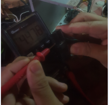
Medición correcta del conector de +5V.
Correct measurement of the + 5V connector.
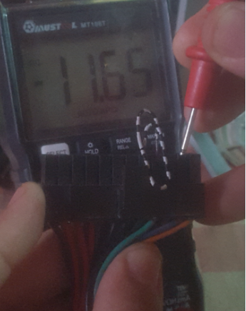
Medición correcta (Dentro del rango) del conector -12V.
Correct measurement (Within range) of connector -12V.
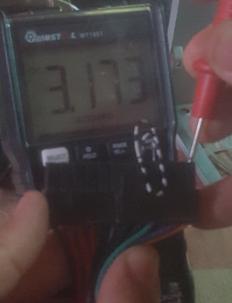
Medición correcta del conector +3.3V. Dentro de los límites aceptables.
Correct connector measurement + 3.3V. Within acceptable limits.
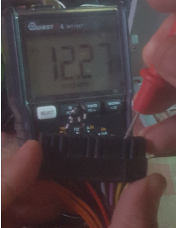
Medición correcta del conector +12V, dentro de los límites de aceptación.
Correct measurement of the + 12V connector, within the limits of acceptance.
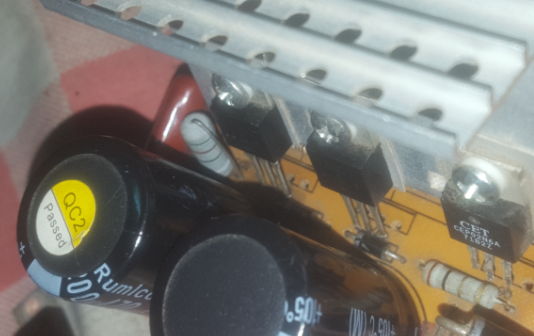
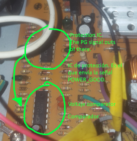
After having assembled everything, I could notice that there was a small problem in the output of the PWR_GOOD connector, which is a protection system that all computer power supplies have, which consists of a self-check of voltage values, when the tension stabilizes completely, it is when the source can already be used. It is a + 5V signal that the motherboard interprets as "OK" to proceed to safely use the power without damaging any component of it. After a hard task of tracking, measurements and everything else, I managed to find the fault: Deficient voltage was coming from the primary supply (AC), and when a problem is like this, it is almost always associated with the input capacitors, and if not these, the problem is already the controller IC which I will show in the following photo:
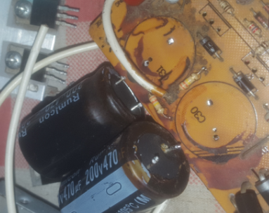
Therefore, I proceeded first to measure capacitors, and after having measured I was able to determine that the two capacitors were in poor condition. One of them had no fixed measurement value and below 1UF (When it should be 300uF), and the other only measured 200uF. They were damaged.
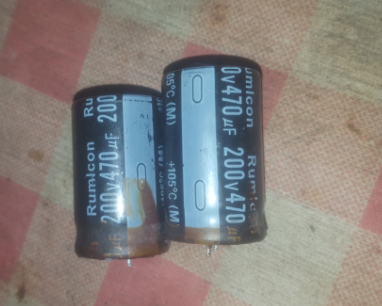
Estos son los capacitores principales. Lamentablemente no los tengo (Ni siquiera usados) para reemplazarlos y corroborar que en verdad sean estos los causantes de la falla. Sino, directamente se debe reemplazar el IC de protección (El que señalé arriba).
These are the main capacitors. Unfortunately I do not have them (not even used) to replace them and corroborate that these are really the cause of the failure. If not, the protection IC must be replaced directly (the one I pointed out above).
Así que esta reparación continuará en otro post, la parte 2, apenas tenga los repuestos para cambiarlos y contarles si resultó correcta la reparación.
So this repair will continue in another post, part II, just have the spare parts to change them and tell them if the repair was correct.
¡Gracias por leer el post! Estén atentos a nuevas actualizaciones referente al mismo. Si tienen alguna duda o sugerencia, no duden en contactarme.
Agradezco enormemente a @appreciator, @blocktrades, @hive.curation y @cervantes por todo el apoyo prestado.
Nos vemos en la próxima amigos.
Thank you for reading this post! Stay tuned for new updates regarding it. If you have any questions or suggestions, do not hesitate to contact me.I am very grateful to @appreciator, @blocktrades, @hive.curation and @cervantes for all the support provided.
See you next time, friends.

Congratulations @alejandrop! You have completed the following achievement on the Hive blockchain and have been rewarded with new badge(s) :
You can view your badges on your board And compare to others on the Ranking
If you no longer want to receive notifications, reply to this comment with the word
STOPTo support your work, I also upvoted your post!
Do not miss the last post from @hivebuzz:
Support the HiveBuzz project. Vote for our proposal!
Me has sorprendido con este pots, te felicito mi amigo.
Gracias por profe bella